EasyManua.ls Logo

IDEAL HP290 - R290 Outdoor Unit Wiring Without Indoor Unit; Figure 69. R290 Outdoor Unit Wiring Diagram

IDEAL HP290
160 pages
Print Icon
To Next Page IconTo Next Page
To Previous Page IconTo Previous Page
Loading...
Appendix
130 Installation and Maintenance
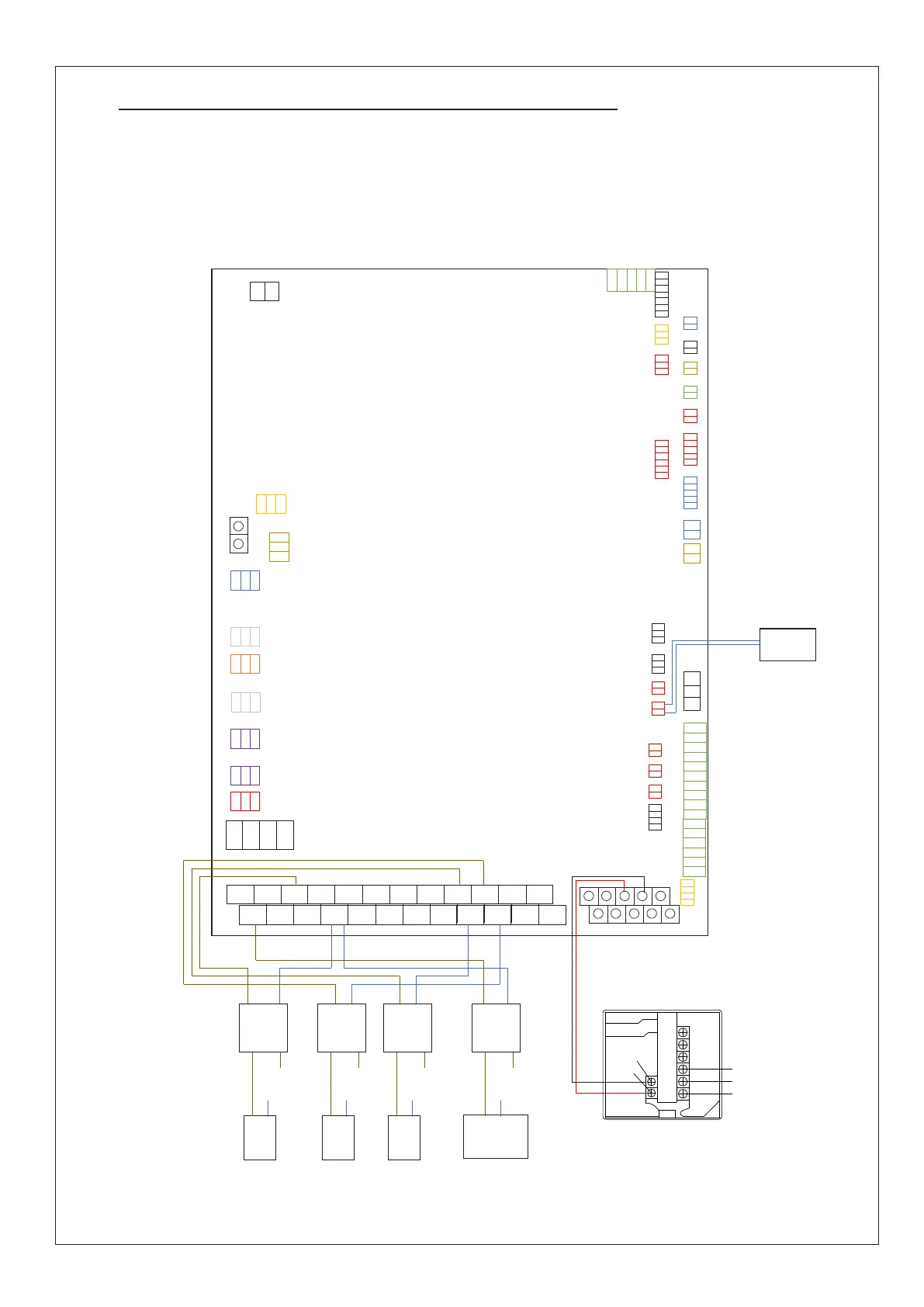
1.3 R290 OUTDOOR UNIT WIRING WITHOUT INDOOR UNIT
If the outdoor unit is to be installed without using the associated Ideal R290 DHW Cylinder or the Ideal R290 Control box, then
the system should be wired as follows.
Note 1: The DHW Immersion Heater must be powered via a contactor, as otherwise the PCB contacts will become welded shut.
Note 2: CH1 & CH2 Pumps must be powered via separate relays, as otherwise the PCB contacts will become welded shut.
Wired
Controller
CN21
CN28
CN68
CN
56
CN71
CN62
CN40
CN41
CN29
CN42
CN32
CN22
CN11
CN30
CN
9
CN61
CN63
CN
36
CN31
CN
66
CN18
CN15
CN38
CN13
CN24
CN37
CN20
CN8
CN39
CN10
CN
47
CN33
CN50
CN5
CN7
CN
45
CN
34
CN46
CN3
CN43
CN35
CN17
AHS2
2
AHS1
1
1ON
3
1OFF
4
2ON
5
2OFF
6
3ON
7
3OFF
8
P-c
9
P-o
10
P-s
11
P-d
12
IBH2
14
TBH
13
IBH1
15
C1
16
C1
17
C1
18
C1
19
C1
20
C1
21
C1
22
C1
23
P-x
24
N
L
Immersion
Heater
DHW (T5)
Thermistor
3 Way
Valve
N
L
N
L
Coil
Contacts
Relay
CH1
Pump
N
L
N
L
Coil
Contacts
Relay
CH2
Pump
N
L
N
L
Coil
Contacts
Relay
N
L
Coil
Contacts
Contactor
D1
D2
E D
H1
H2
E_H
X1/HB
X2/HA
Figure 69. R290 Outdoor unit wiring diagram

Table of Contents

Related product manuals