Section 9 - Fault Finding
96 Installation and Maintenance
FAULT FINDING
9.1.3 Live and Neutral reversed
Is the two-way wiring assembly between the Outdoor
Unit and the Indoor Unit correctly connected?
Refer to Figure 41 on page 39)
Is the two-way wiring assembly from the Indoor PCB to
the User Interface PCB, connected correctly?
Replace the User Interface. If the fault continues,
replace the Outdoor PCB.
Make sure that the two-way wiring
assembly between the Outdoor Unit and
the Indoor Unit is correctly connected.
Make sure that the two-way wiring
assembly between the Indoor PCB and
the User Interface PCB is connected
correctly?
NO
NO
YES
YES
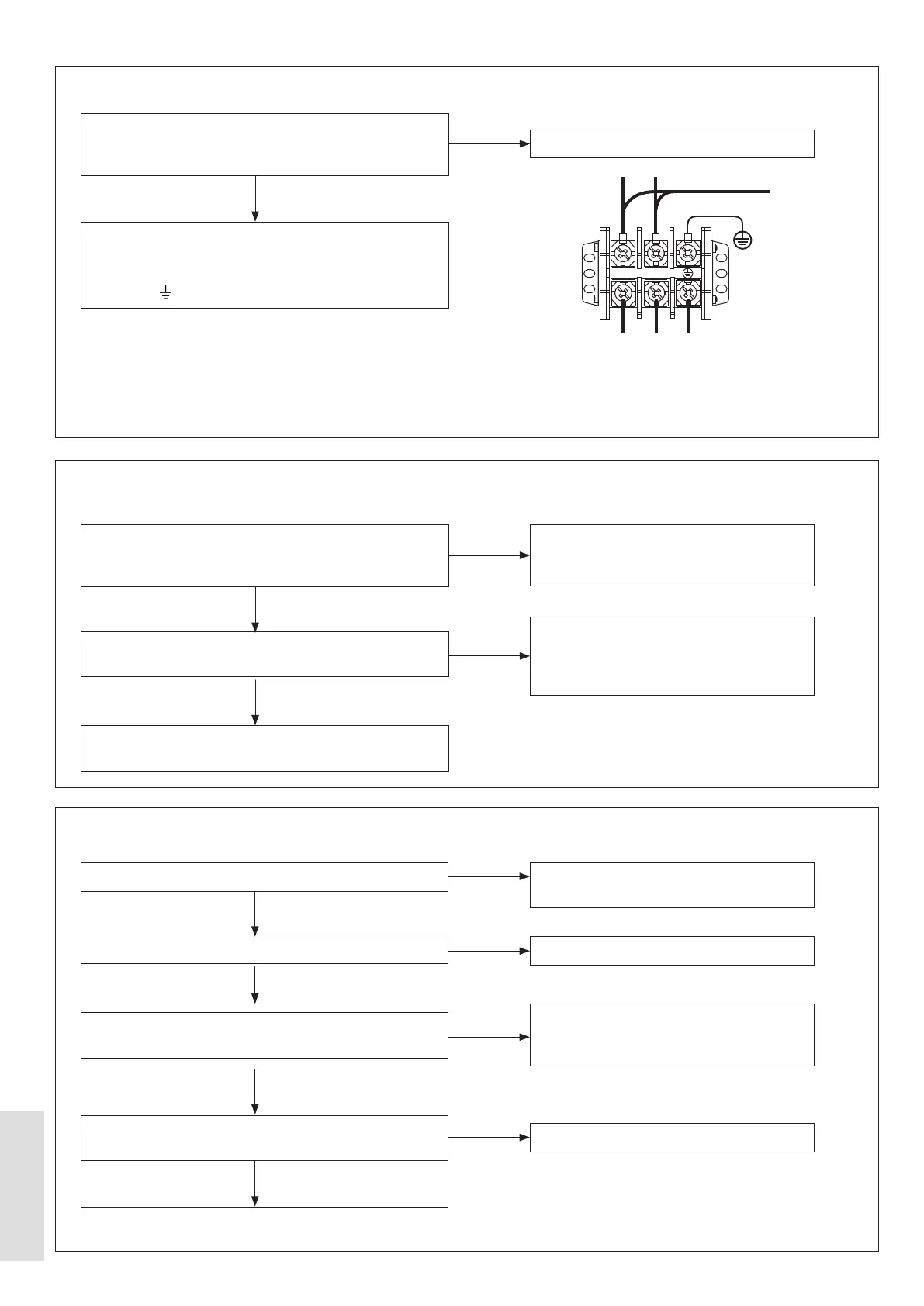
9.1.4 No connection Outdoor PCB to User Interface
Are the LIVE and NEUTRAL wires of the external
mains wiring assembly cross-connected at the XT1
Connector? Refer to Figure 64
Make sure that the mains power supply connections are
not cross-connected.:
L = LIVE = Brown wire, N = NEUTRAL = Blue wire, and
= EARTH = Yellow / Green wire.
Replace the Outdoor PCB
YES
NO
BROWN
XT1
BLUE
Y/G
L N
POWER SUPPLY
Lowest permitted - 240 V AC
L N E
Figure 64. XT1 Connector
9.1.5 Header Thermistor (T1) Error – for cascade and hybrid
Is this a Cascade or a Hybrid system?
Is a Header Thermistor connected?
Is the wiring for the header thermistor correctly
connected to Outdoor PCB?
Disconnect the Header Thermistor. Check that the
Replace the Outdoor PCB.
User interface settings are incorrectly set.
Refer to 5.8 on page 59.
Connect the Header Thermistor.
Make sure that the wiring assembly from
the Header Thermistor is connected to the
Outdoor PCB.
Replace the header thermistor.
NO
NO
NO
NO
YES
YES
YES
YES