Section 4 - Installation
INSTALLATION
39
Installation and Maintenance
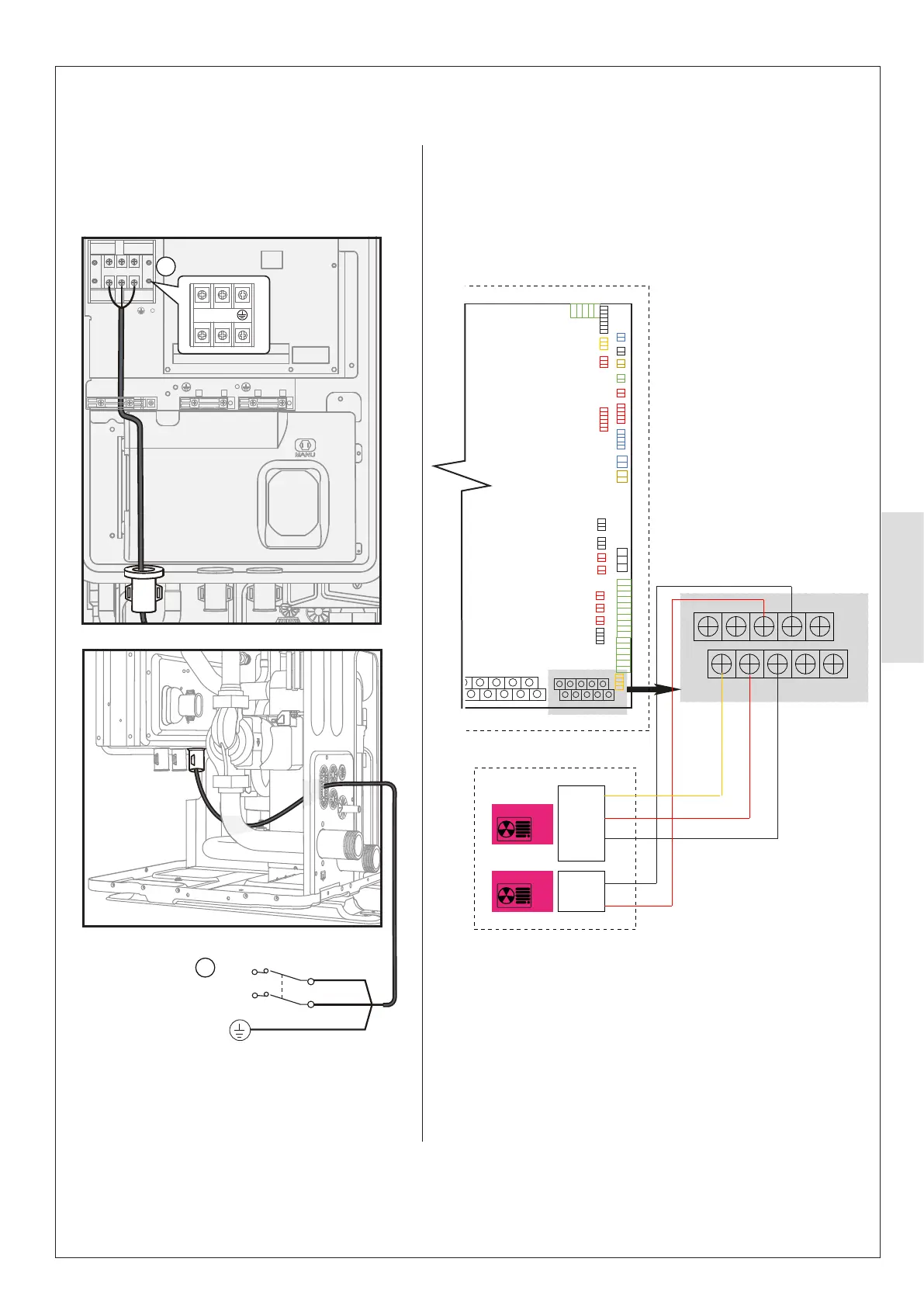
3 phase without backup heater.
Main power supply
L
N
L
N
A
A
Figure 40. Mains Supply Connections to Outdoor Unit Figure 41. Communications Connections between
Outdoor Unit and Control Box
A B X/HA Y/HB E
T1 T2 E1 H1 H2
X/HA
T1
T2
E1
Y/HB
Not used
T1
T2
E1
Outdoor Unit
XHB
XHA
Outdoor
Unit
Outdoor Unit
Indoor Unit
ⓘ IMPORTANT:
If the Ideal Indoor Control Box is being used, set dip-switch
S2 (switch 1) to ON.
If the Ideal HP290 Controller is being used, set dip-switch
S2 (switch 1) to OFF. Refer to Sect 5.5.1