Section 5 - Commissioning
COMMISSIONING
53
Installation and Maintenance
ᘐ WARNING: Prior to activating the control box, make
sure that all requirements and checks from sections 5.1
and 5.3 have been completed. Electrical circuits require
verication of safety to reduce risk of electric shock or
damage to the system.
ᘐ WARNING: The Heat Pump must have the power
active for a minimum of 6 hours prior to activation of the
heating function to protect the compressor.
5.5 ACTIVATION OF SYSTEM
SCAN
for HP290 USB
Commissioning
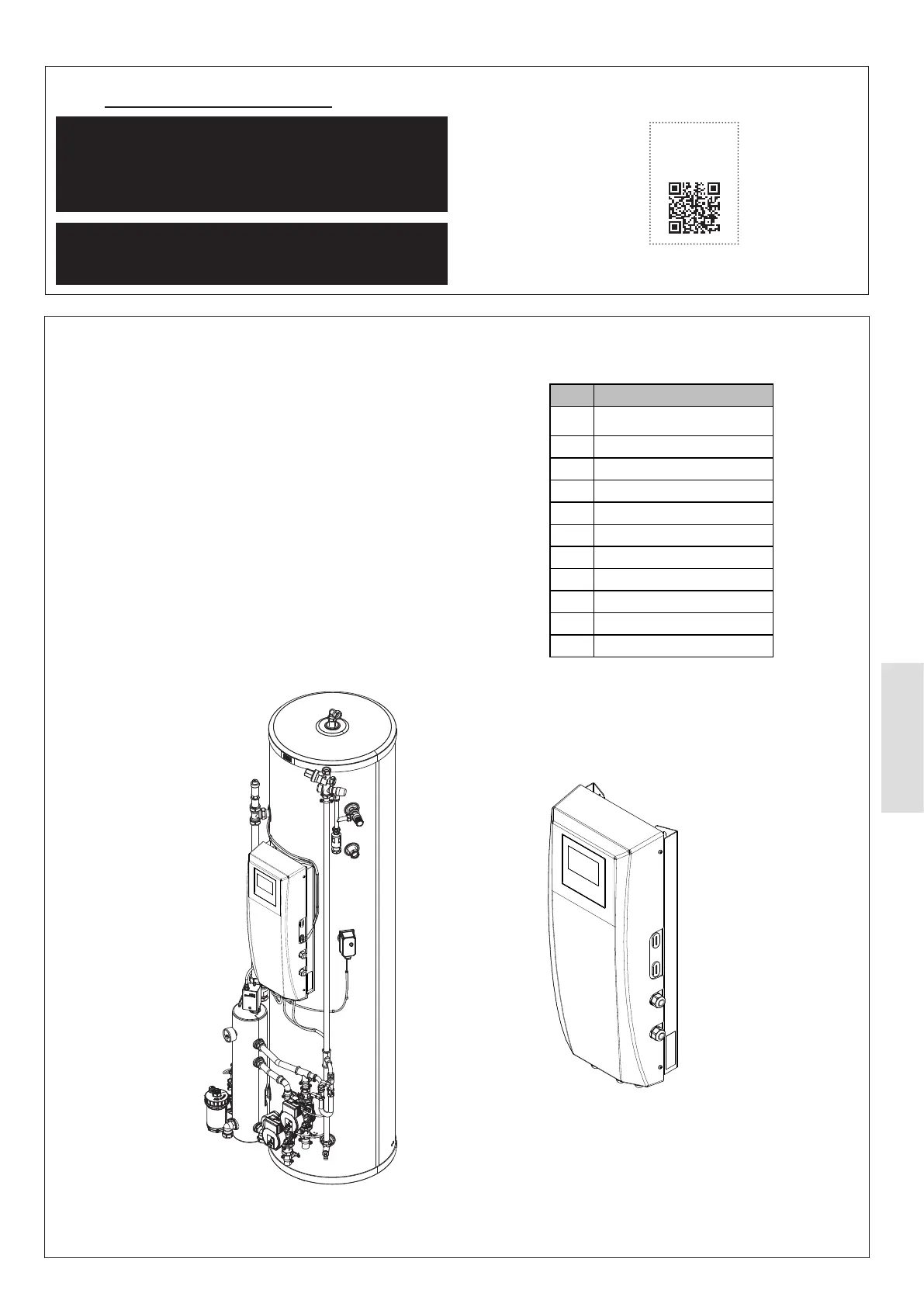
Table 18 USB changed parameters
5.5.1 HP290 Cylinder or HP290 Control Box
1. Remove the HP290 Monobloc top and side panels.
Refer to Sect 4.1.7 Accessing the Casing.
2. Gain access to the HP290 Monobloc Outdoor Control
PCB (see Figure 53). Remove and keep the Control
Box cover retaining screws and remove the cover.
3. Make sure that DIP switch S2 (switch 1) is set to the
ON position, see Figure 55.
4. Update the system parameters using the supplied USB.
Refer to Sect 5.5.3. For system parameters see Table
18.
5. Put the Control Box cover in position and install the
cover retinaing screws.
6. Install the HP290 monobloc top and side panels. Refer
to Sect 4.1.7 Accessing the Casing.
or
HP290 Controller
with Control Box
HP290 Control Box
Figure 52. Types of HP290 Control Box which require DIP Switch S2 Position 1 to be set to ON
Item Parameter
1 dT5_ON
2 T4DHWMIN
3 T5S_DISINFECT
4 T_DHWHP_MAX
5 Cooling Mode
6 T4HMAX
7 T4HMIN
8 Zone 2 H-emission
9 Room thermostat
10
T4_AHS_ON
11