Section 3 - Pre-Installation Checks
PRE-INSTALLATION
27
Installation and Maintenance
3.3.6 Protective Safety Zone
ᘐ WARNING: The product contains the hydrocarbon
refrigerant R290 which is very ammable. The refrigerant
may mix with air to form a ammable atmosphere
increasing the risk of re and/or explosion.
Work that requires the removal of the exterior casing of
the Heat Pump must only be carried out by competent
persons who are familiar with the risks of R290 refrigerant.
Work on the refrigeration circuit must only be carried out
by a Cat I or Cat II F-gas certied engineer with a City and
Guilds 6187-21 certicate or equivalent. Work done on the
heat pump should be done in accordance with industry
standard safety procedures and practices for working with
hydrocarbons.
The refrigerant circuit of the outdoor heat pump is charged
with R290 refrigerant, which is an odourless, colourless, and
accordance with ISO 817 and ANSI/ASHRAE standard 34.
When selecting an installation area, it should be considered that
R290 has a higher density than air and therefore in the event of
leakage from the heat pump, will displace air and pool in low-
to prevent explosive and asphyxiating atmospheres, by avoiding
the following within this area:
1. Building openings, e.g., doors, windows, air intakes,
exhausts, cellar entrances, etc.
2. Ignition sources, e.g., electrical switches, plugs sockets,
drills, heaters, etc.
3. Areas outside of the property lines e.g., public areas,
adjacent buildings.
4. Ditches, troughs, or depressions in the ground.
5. Surfaces exceeding 400°C in temperature.
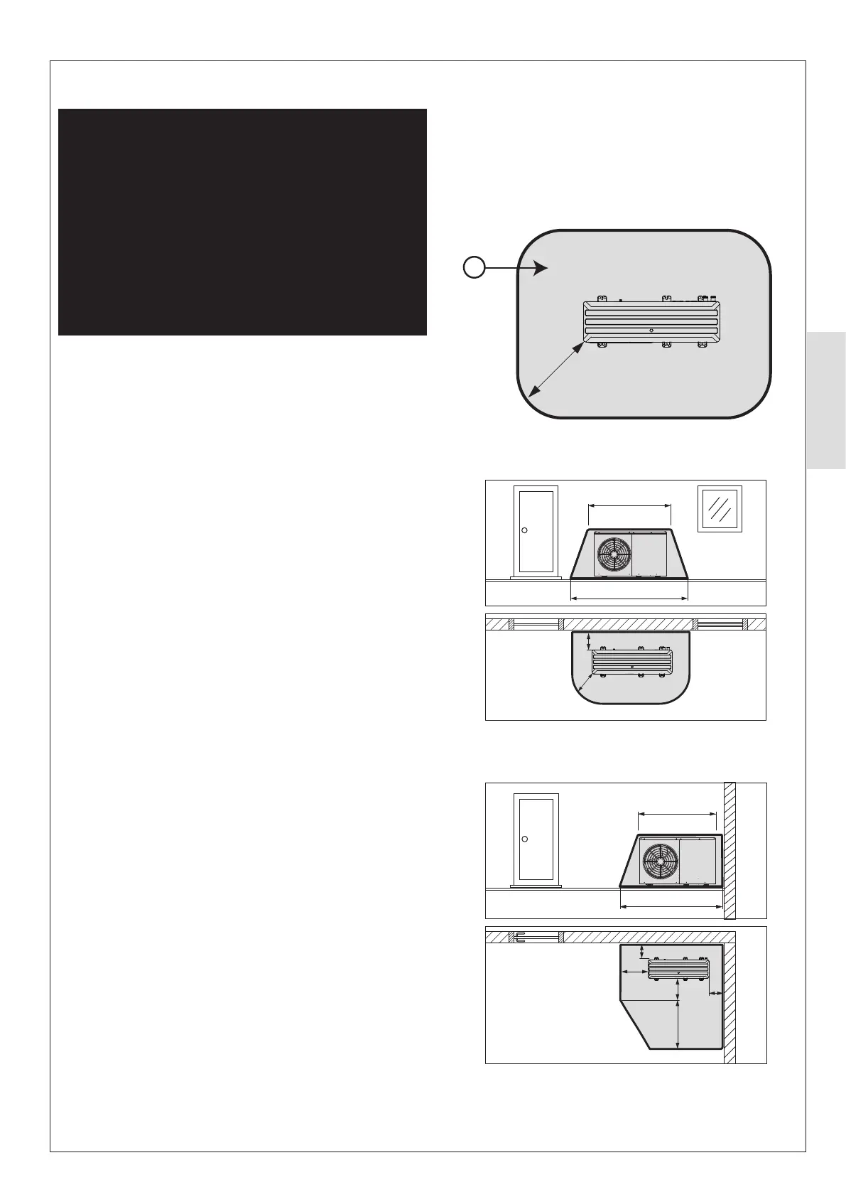
The protective safety zone is dependent on the installation
areas and adjacent structural installations. See Figure 28,
Figure 29 and Figure 30 to determine the extent of the
protective safety zone.
In this area no further works should be carried out which would
zone.
For all shown types of installations, the top of the
protective safety zone is in line with the top face of the heat
pump.
Figure 28. Freestanding installation
Figure 29. Installation in front of wall
Figure 30. Installation in corner
1000mm
A
≥300mm
1000mm
2400mm
3400mm
2400mm
2900mm
300mm
500mm
500mm
500mm
1800mm
A - Safety Zone
ⓘ IMPORTANT: Dimensions shown in Figure 28, Figure
29 and Figure 30 below are the minimum dimensions for
the extent of the protective safety zone.
500mm Minimum