Section 1 - General
GENERAL
8 Installation and Maintenance
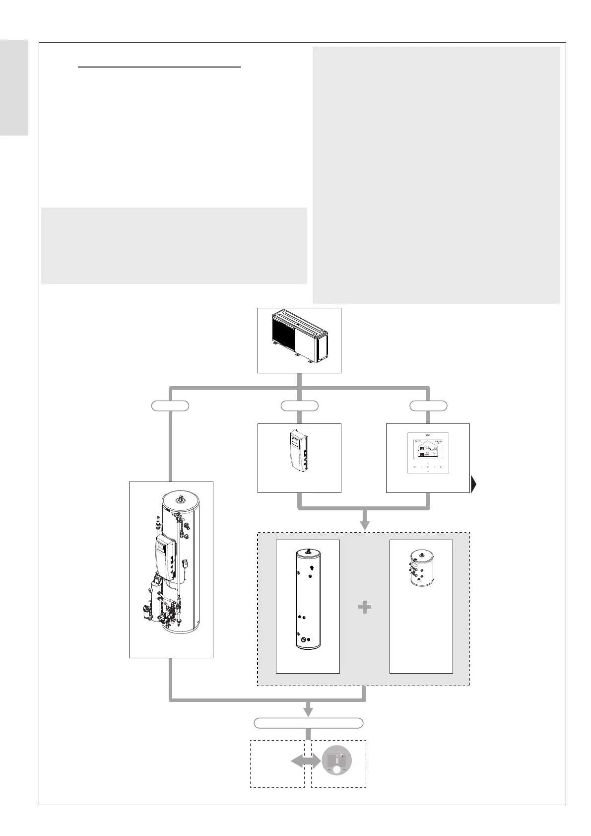
1.5 SYSTEM CONFIGURATIONS
Figure 1.
For further information on available HP290 accessories, refer to
Section 3.1 System Combinations on page 24.
For further information on HP290 Cylinder and associated
component options, refer to Table 10 in Section 2.5.2 DHW
Cylinders on page 21.
For further information on HP290 Cascade refer to APPENDIX
1.4 HP290 Cascade wiring.
For further information on appliance package contents, please
refer to Section 4.1.3 Receival and Unpacking on page 31.
Option 1:
HP290 Monobloc Air Source Heat Pump
+
HP290 Pre-Plumbed Cylinder
+
Halo Lite RF
Figure 1. System Congurations
HP290
OPTION 2 OPTION 3
OPTION 1
3rd Party
PRT
HP290 Control Box Heat Pump Controller
HP290
Cylinder and Control Box
Halo Lite RF
Programmable Room Heat Pump Thermostat
OR
12 12
Sat, 17 Nov
cancel
override
10:33pm
0 0
target temp
until 12:33am
current room
temp
Zone1
129
40
40
40
-
Zone2
E01
Heat Pump
DHW Cylinder
Buffer Cylinder
(if required to meet
minimum system
volume/flow rates)
Option 2:
HP290 Monobloc Air Source Heat Pump
+
HP290 Control Box
+
Heat Pump DHW Cylinder
+
Flow Rates)
+
Halo Lite RF
Option 3:
HP290 Monobloc Air Source Heat Pump
+
Heat Pump Controller
+
Heat Pump DHW Cylinder
+
Flow Rates)
+
Halo Lite RF
Refer to Appendix 1.3 R290
Outdoor Unit Wiring without
Indoor Unit Control Box.
Optional