Section 6 - Inspection and Maintenance
INSP & MAINT
86 Installation and Maintenance
6.3 HEAT PUMP SERVICE & MAINTENANCE PROCEDURE
ᘐ WARNING: Before removing any covers or casing,
make sure that the electrical power supply is isolated.
ᘐ CAUTION: Any damage to paint is to be repaired
using a suitable paint to prevent corrosion of the casing
and compromising the assembly.
ᘐ CAUTION: Compressed air and high pressure water
jets i.e. pressure washers must not be used on the heat
pump. The use of high pressure water jets will damage
the unit.
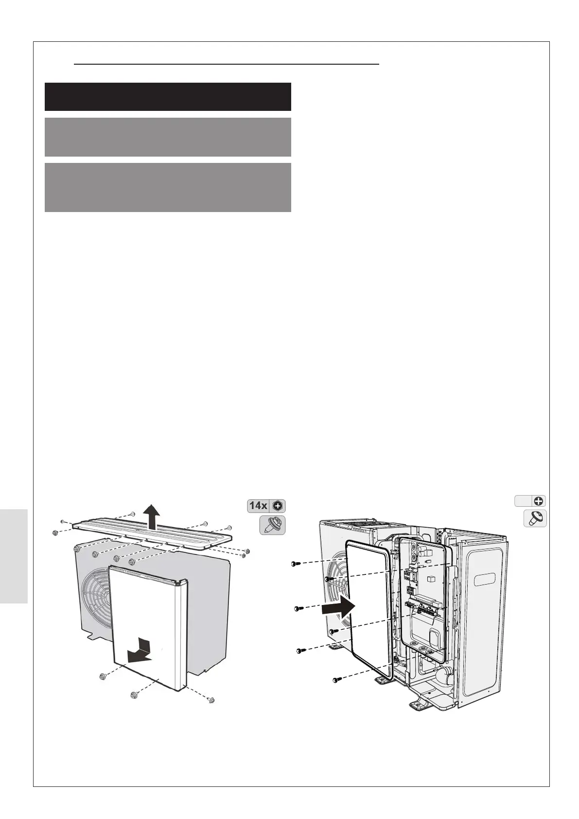
Figure 61. Heat Pump - Top and side panel installation Figure 62. Heat Pump - Electrical panel installation
6.3.1 HP290 Monobloc Heat Pump Checks
1. Do a check of the installation to make sure that it
conforms to the installation instructions and correct any
non-conformities.
2. Check that the installation is electrically supplied by
correctly rated circuit breakers (check values against
Table 1 on page 9 & Table 9 on page 20).
3.
heat pump.
4. Remove the top and side panels by removing the screws
shown in Figure 61. To gain access to the electrical panel,
remove the 6 screws indicated in Figure 62. (See section
4.1.7 for thorough instructions).
5. Do the following internal checks:
a. Check electrical connections, cables, and terminals
for signs of damage, loose connections etc.
b. Check the refrigerant circuit for signs of leakages,
such as oil deposits.
c. Release air from the auto air vent and the auto air
vent must remain open at all times. (Check system
pressure afterwards and repressurised if necessary).
6.
7.
each corner with a terminal screwdriver and then remove
the 4 screws underneath. Slide the fan grille upwards to
remove from casing.
8. Check that the fan assembly is unobstructed, and spins
evenly. Clean the fan impeller assembly using a proprietary
cleaner.
9. Check the condition of the evaporator for corrosion,
damage, blockage, and repair where necessary.
10.
and a proprietary cleaner. Make sure to remove all dirt and
debris.
11.
12. Clean the outer casing panels.
13. Check the condition of the pipework insulation and repair
where necessary.
14.
15. Check and record the levels of glycol and inhibitor in the
system.