Section 5 - Commissioning
COMMISSIONING
51
Installation and Maintenance
5.2.2.3 Antifreeze Valves
w
[
' '
�-t -�
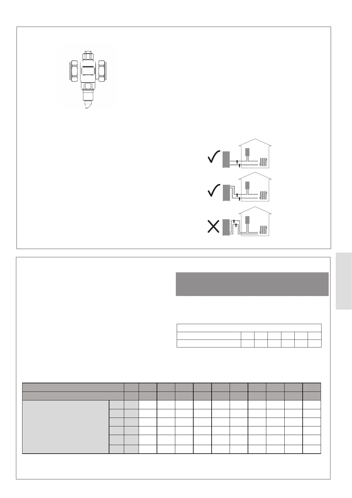
Figure 49. Typical Antifreeze Valve
Installation
Refer to Antifreeze valve manufacturers installation instructions.
Below is general guidance on the installation requirements.It
must be made sure that the antifreeze valves are suitable for
both the ambient-air, and water temperature range.
installed in the vertical position as depicted. It must be free from
obstructions to enable servicing.
The antifreeze valves must be installed outside, in the coldest
part of the system that is at risk of freezing.
We recommend installing the antifreeze valves on both pipes
Figure 50.
They must not be placed close to heat sources which could
interfere with proper function.
Leave at least 15 cm clearance from the ground so the block
of ice that may form below will not prevent the safe operation
of the valve. Keep a distance of at least 10 cm between the
antifreeze valves.
When installed outdoors, the anti-freeze valve must be
protected from rain, snow and direct sunlight.
Figure 50. Antifreeze Installation Recommendations
5.2.2.4 Glycol Antifreeze Treatment
Ideal Heating recommend dosing the system with a suitable
inhibitor as a minimum. If propylene glycol is used for frost
protection, a combined propylene glycol, biocide and inhibitor
MUST be used.
ⓘ IMPORTANT: When dosing the system with any
product, the use of ll and ush valves in conjunction
with a ll and ush station is recommended to make sure
the concentration and mixing is thorough and avoid the
potential for hydrostatic locking of the system.
ᘐ CAUTION: Table 17 is to be used for guidance only.
Consult the glycol providers instruction for exact dosage
and recommendations for use.
The values in Table 16 illustrates the freezing point of the water
when dosed with propylene glycol mixtures.
Table 16 Glycol Concentration vs Expected Min. Outdoor Temp.
Freezing Point
Propylene Glycol Solution ( %) 0 10 20 30 40 50
Temperature (°C) 0 -3 -8 -14 -22 -34
The below values in Table 17 illustrates the heating capacity reduction when dosed with propylene glycol and when maintaining
Table 17 Glycol Concentration vs Performance
Propylene Glycol Volume in Water % 0 10 15 20 25 30 35 40 45 50
Capacity Reduction Factor - 1 0.98 0.973 0.96 0.95 0.935 0.919 0.895 0.88 0.85
Heating Capacity
4.5 kW 4.5 4.41 4.38 4.32 4.28 4.21 4.14 4.03 3.96 3.83
6 kW 6 5.88 5.84 5.76 5.7 5.61 5.51 5.37 5.28 5.1
8 kW 8 7.84 7.78 7.68 7.6 7.48 7.35 7.16 7.04 6.8
10 kW 10 9.8 9.73 9.6 9.5 9.35 9.19 8.95 8.8 8.5
12 kW 12 11.76 11.68 11.52 11.4 11.22 11.03 10.74 10.56 10.2
14 kW 14 13.72 13.62 13.44 13.3 13.09 12.87 12.53 12.32 11.9