Section 5 - Commissioning
COMMISSIONING
54 Installation and Maintenance
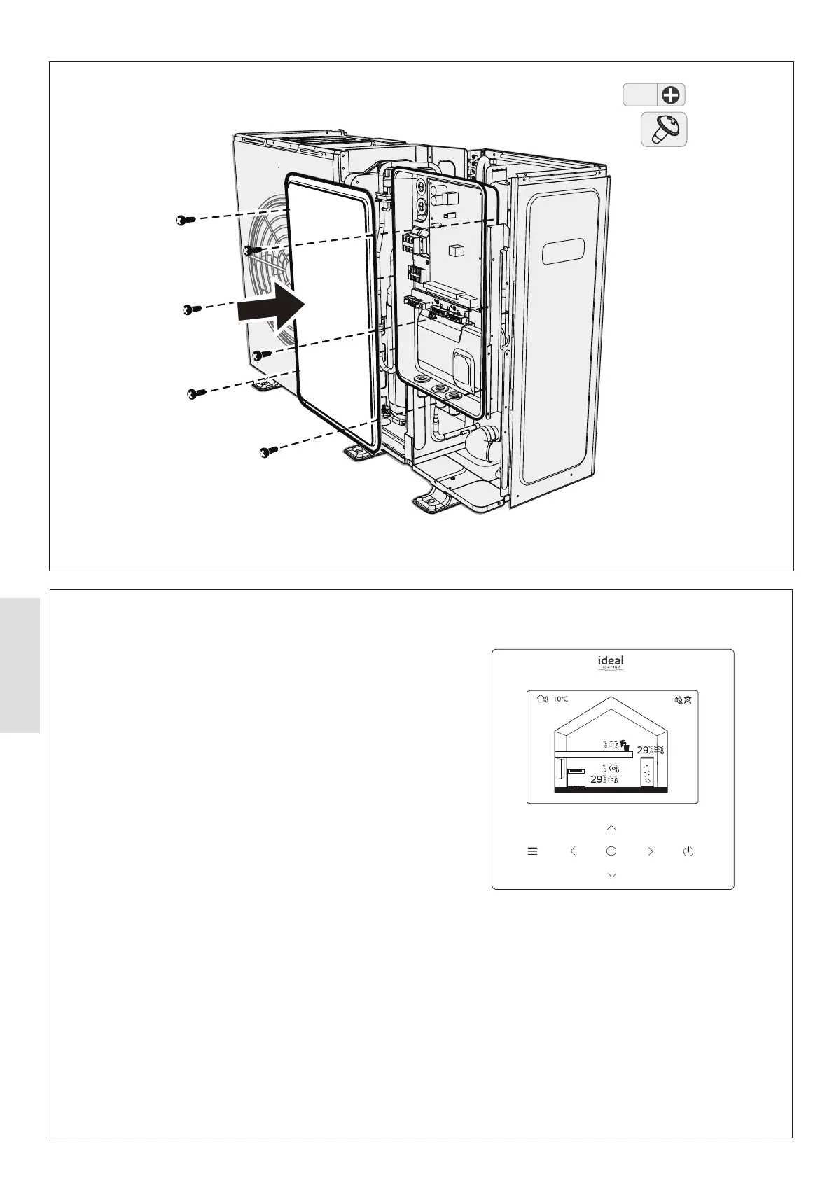
Figure 53. HP290 Monobloc (Access to Outdoor Control PCB)
Zone1
40
40
Figure 54. HP290 Heat Pump Controller
5.5.2 HP290 Controller
Set the HP290 Monobloc DIP switch as follows:
1. Remove the HP290 Monobloc top panels. Refer to Sect
4.1.7 Accessing the Casing.
2. Gain access to the HP290 Monobloc Outdoor Control PCB.
Remove and keep the Control Box cover retaining screws
and remove the cover.
3. Make sure that DIP switch S2 (switch 1) is set to the
OFF position, see Figure 55.
4. Update the system parameters using the supplied USB.
Refer to Sect 5.5.3. For system parameters see Table 18.
5. Put the Control Box cover in position and install the cover
retinaing screws.
6. Install the HP290 monobloc top and side panels. Refer to
Sect 4.1.7 Accessing the Casing.