PRE-INSTALLATION
24 Installation and Maintenance
Section 3 - Pre-Installation Checks
3.1 SYSTEM COMBINATIONS
ᘐ WARNING: Failure to comply with this
documentation will lead to increased risk of injury or
death to persons, or damage to the product or property.
ⓘ IMPORTANT: Any combinations of the products
that are not listed below are outside of the scope of this
document and are not covered under warranty and are
excluded from liability.
The available product combinations are:
• HP290 Monobloc Heat Pump+ HP290 Pre-plumbed Cylinder
(HP290 Control Box Included)
• HP290 Monobloc Heat Pump + HP290 Control Box (wall
mounted) + Heat Pump DHW Cylinder (if DHW is required)
• HP290 Monobloc Heat Pump + HP290 Controller + Heat
Pump DHW Cylinder (if DHW is required).
ᘐ WARNING: Installations must conform to the
schematics in Appendix 1.1. It is the responsibility of the
installer to make sure that all appropriate measures are
implemented including appropriate safety devices.
Refer to Appendix 1.1 System Schematics on page 118 for
System Schematic & arrangement details.
3.2 PRIMARY HEATING SYSTEM REQUIREMENTS
To safeguard correct function of the system it must be made
in Table 11.
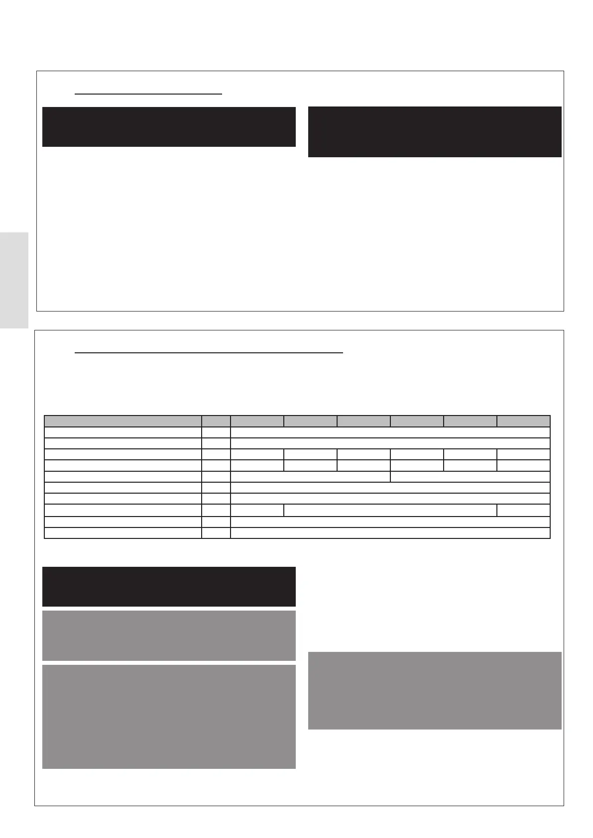
Table 11 System Specication
Specication/Requirement Units 4.5 kW 6 kW 8 kW 10 kW 12 kW 14 kW
Maximum System Operating Pressure
bar 3.0
Minimum System Pressure
bar 1.0
Maximum Flow Rate (l/min) 15.0 20.8 35.0 41.7 45.8 50.0
Design Flow Rate (l/min) 11.7 17.5 29.2 35.0 40.8 46.7
Minimum Flow Rate (l/min) 6.7 11.7
Maximum Water Temperature °C 75
Minimum Water Temperature °C 12
Primary Circuit Minimum Copper Pipe (ø)
*
mm 22 28
35
Minimum System Filter Mesh Size µ 800
Minimum Water Volume L 40
*
Consideration of the internal diameter of selected pipework must be taken
into account when calculating the system resistance and water velocities
at the specied design ow rates.
ᘐ WARNING: It is the responsibility of the installer to
make sure that the correct safety devices are installed to
the heating system.
ᘐ CAUTION: The system pipework must be designed
and installed to achieve the correct Design Flow Rate.
Failure to achieve the correct design rate will lead to poor
performance and eciency.
ᘐ CAUTION: The system ow rate must be guaranteed
to be above the minimum ow rate requirement in all
operating modes, taking care when the installation
includes thermostatic / electronic control valves. If the
minimum ow rate of the system is not maintained at
all times, the Heat Pump will not operate. The water
velocity in the pipe should be kept within limits of
material to avoid erosion, corrosion, and excessive noise
generation.
ⓘ IMPORTANT: Added resistance in the hydronic
circuit will result in the reduction of the overall system
eciency. To reduce resistance, as few bends must be
used as possible and swept bends are to be used where
practical. The cross-sectional area of the pipework must
be maintained and meet the minimum size.
3.2.1 Minimum System Volume of the Primary
Heating Circuit
ᘐ CAUTION: The primary circuit of the heat pump must
have a minimum free system volume of 40L at all times.
This makes sure that the Heat Pump does not cycle
excessively and is able to defrost completely. Failure
to adhere to this requirement will result in inecient
operation of the Heat Pump and the potential for
nuisance faults.
Free volume shall be considered as any part of the system
with un-valved sections of pipework and radiators without
Thermostatic Radiator valves (TRV).
If the minimum free volume cannot be met this will need to
be increased. This can be achieved with the addition of a
ⓘ IMPORTANT: Make sure prior to the installation that permissions have been granted for the installation.