Section 4 - Installation
INSTALLATION
44 Installation and Maintenance
4.3 INSTALLATION OF CONTROL BOX
4.3.1 Receival and Unpacking and Handling
Note: Section 4.3.1 is only applicable if using a non pre-
plumbed cylinder, as the control box will be packaged and
supplied separately.
Packaging Symbols
Below are the symbols on the packaging of the control box
when supplied as an individual unit. The below symbols and
conditions must always be followed for the packaged product.
Contents of Package. Checklist.
After the product is unpacked, make sure that all the contents
are present.
Quantity Item Description
1 HP290 Control Box
1 Literature Pack
1 Wall Mounted Fixing Kit
1 Connector Kit
1 Domestic Hot Water Thermistor
1 Wall Template
ⓘ IMPORTANT: If there are any missing items, contact
Ideal Heating.
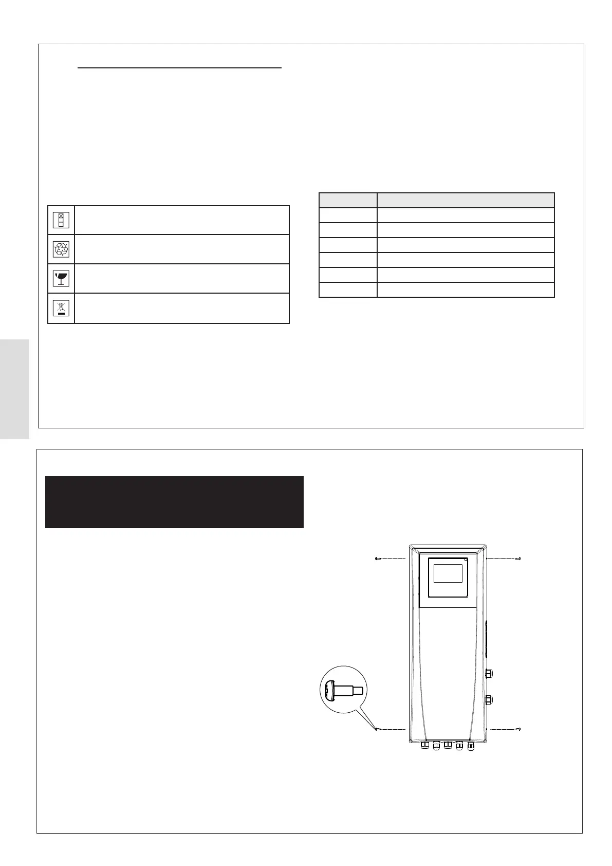
ᘐ WARNING:
The control box may have dual electrical
supplies (a power supply for the control box & a power
supply from a hybrid boiler). Both must be isolated before
removing the control box front panel.
Figure
44.
the control box and make sure that the sides of the front panel
are external to the control box. Then reinsert and tighten the
avoid damage to the front panel.
4.3.2 Removal of the Front Panel
Figure 44. Front Panel Removal
2
Stackable height x 2
This package is recyclable
Product must be treated as fragile
Product should not be discarded as unsorted waste but
must be sent to separate collection facilities for recovery
and recycling