Section 2 - Product Information
PRODUCT INFO
23
Installation and Servicing
2.7 HEAT PUMP OPERATING PRINCIPLES
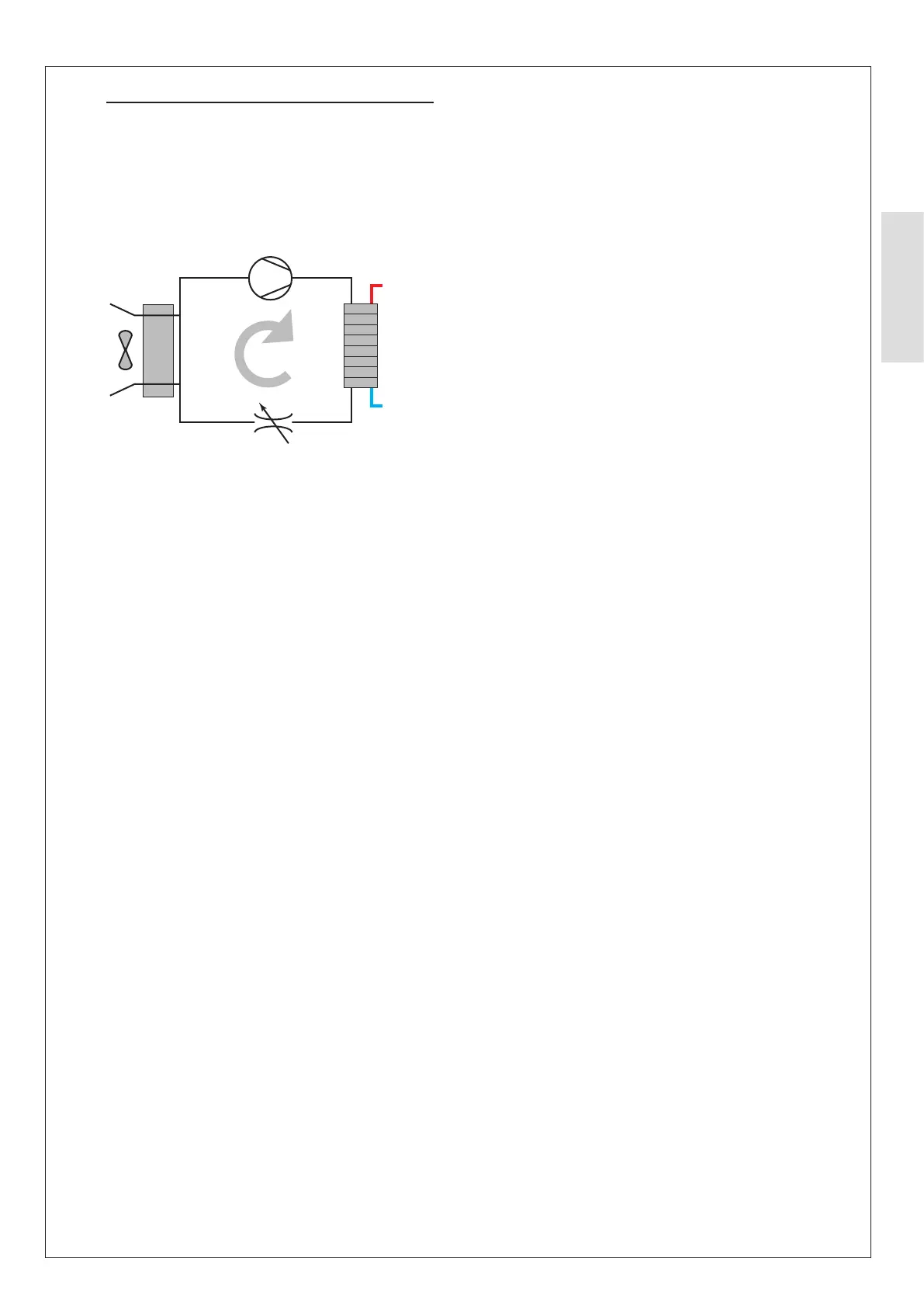
2.7.1 Operating Principle
The Heat Pump contains a closed refrigerant circuit. When
operating, refrigerant is circulated around the circuit absorbing
heat energy from the ambient air, increasing its temperature
and transferring it to the heating and hot water systems
through a heat exchanger.
1
4
Figure 26. Closed Refrigerant Circuit
The circuit consists of four main components/functions.
1. Refrigerant absorbs heat energy during vaporisation when
2. The compressor increases the pressure and temperature
of the vapour refrigerant.
3. As refrigerant changes state to liquid in the condenser
(heat exchanger) it transfers heat energy into the primary
system water.
4. The expansion valve reduces the pressure and
temperature of the liquid refrigerant to begin the
vaporisation process and repeat the cycle.
For an in-depth refrigerant circuit schematic see Appendix 1.2.4.
2.7.2 Defrost Method
During operation, the Heat Pump will periodically be required
to go through an automatic defrosting process dependant on
the outdoor conditions. Over time the evaporator will begin to
collect frost from the water vapour in the air.
The defrost process causes the refrigerant to be directed to
the evaporator and uses the hot vapour to thaw the frost into
liquid water. This liquid water then collects in the base panel
base panel.
2.7.3 Domestic Hot Water
If there is a domestic hot water (DHW) cylinder installed and
the temperature of the DHW cylinder is less than the Hot
Water Set point minus the hysteresis then the heat pump
circuit is activated and directed (via the divertor valve) to
heat the DHW cylinder. The Heat Pump and primary circuit
circulation pump will be active until the DHW Cylinder has
reached its setpoint.
This function will always take priority over the heating of the
space heating system within the programmed time period. The
two functions cannot operate simultaneously.
2.7.4 Space Heating
If there is a heating demand and the temperature of any
thermostat is less than its setpoint, the primary circuit is
activated and directed (via the divertor valve) to heat the
space heating circuits. The Heat Pump and circulator will
modulate and be active until the space heating has reached its
setpoint.
2.7.5 Anti-Legionella Function
If there is a DHW cylinder installed, Anti-Legionella measures
should be utilised in accordance with HSE guidance HSG274
Part 2.
The control system is provided with an Anti-Legionella
function for the DHW cylinder, the default parameter, which
is adjustable according to installation / user requirements,
initiates this function once per week and heats the DHW
cylinder to hold at 60°C for a period of 15 minutes using both
the heat pump and DHW immersion heater..
2.7.6 Frost Protection
Frost protection is controlled in accordance with the outdoor
temperature, and water temperature sensors on the outdoor
unit. When the frost protection occurs, the outdoor unit
displays the error code Pb and the unit will stop operating.
Frost protection will activate under either of the following
conditions:
- Outdoor temperature < 3°C & minimum water
temperature < 5°C
- Minimum water temperature < 2°C.
Once either of these conditions are met, the primary circulator
the compressor will run for a 10 minutes until the minimum
water temperature is > 15°C.
If the water temperature is < 8°C and there is normal water
applicable) will operate until the minimum water temperature
is met.
The compressor will operate for a minimum period of 10
minutes until the minimum water temperature is > 15°C.
An auxiliary heat source will be active for a minimum period of
5 minutes until the minimum water temperature is > 10°C.