Section 4 - Installation
INSTALLATION
34 Installation and Maintenance
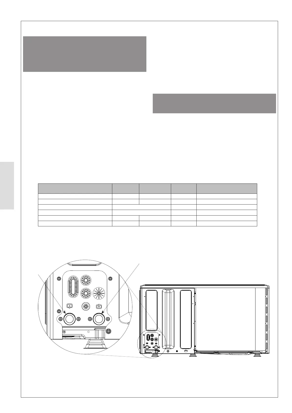
Figure 36. Primary Heating Connections
4.1.6 Hydronic Connections
ᘐ CAUTION: To prevent blockage, care should be
taken to prevent solids, metal llings, sealing tape, and
any other contaminant from entering the heating circuit.
Before connection to the heating system, the pipework
should be thoroughly cleaned in accordance with
BS7593:2019 to remove any contaminant.
The installation of the hydronic pipework must comply with
local directives and guidelines.
To optimise performance, the length of pipes between the
heat pump and the indoor system must be kept as short as
possible and the resistance of the circuit should be minimised
appropriate applications. Where thread sealant is required
use PTFE tape, or sealing pastes (synthetic, dependant on
application). Face seal connections are to be tightened with
15 Nm to 35 Nm.
The diameter of the pipe is to be calculated based on the
rate and length requirements of the hydronic system.
Consideration of the internal diameter of selected pipework
must be taken into account when calculating the system
rates.
The water velocity in the pipe should be kept within the design
limits of the material used to avoid erosion, corrosion, and
excessive noise generation.
rates between 10 - 50L/min is required to be installed on the
primary return pipework
ᘐ CAUTION: When connecting metal pipes of dierent
materials, be sure to insulate the connections to prevent
galvanic corrosion.
It must be made sure that there is no transfer of vibration to
the dwelling or heating system. To protect the heating system
from vibration, braided hoses must be installed between the
heat pump and rigid pipework to prevent vibration from being
transferred to the system.
Local to the heat pump there should be means of isolation
and drainage to allow for temporary decommissioning.
External pipework must be insulated with UV/moisture
Flow
Return
Connection Size
4.5 kW - 6kW
Size
8 kW - 14kW
Material Type
Heat Pump Flow 1'' BSP 1 ¹/'' BSP Brass BSP Male
Heat Pump Return 1'' BSP 1 ¹/'' BSP Brass BSP Male
Pressure Relief Valve Connection (PRV) 9 mm ID PVC Hose
Condensate Disposal Spigot (Base Panel) 32 mm OD Plastic Barbed Spigot
Flow Adaptor (Provided) 1” M – 1 ¼” F 1 ¼” M – 1 ¼” F Brass BSP Parallel Male to Female
Return Adaptor (Provided) 1” M – 1 ¼” F 1 ¼” M – 1 ¼” F Brass BSP Parallel Male to Female
Table 13 Connection Sizes