IDS X-Series Installer Manual 700-398-02H Issued July 2013
Installing a Zone Expander Module
When installing a zone expander module refer to the document supplied with the module. Note that up to 6
bus-wired, 8-zone expander modules (P/N: 860-06-X-08S) and 1 plug-in expander (P/N: 860-06-X-08PI) may be
added to the IDS X64 Alarm Panel. Zones 9-16 are reserved for the Plug-in Zone Expander module which may
be used on the X16 as well.
IDS Remote Receiver
Up to 4 IDS Remote Receivers (P/N: 860-07-X02-DI) may be connected to the keypad Bus. Using this facility
allows remote arming and disarming of the panel while providing user identification for a maximum of 128
remotes.
For a full list of features and benefits of the receiver, please see the manual that comes with it.
Radio Transmitter Connection
When connecting a radio transmitter, use the TX terminal provided on the panel to supply power to the
transmitter. This output is protected by a 4 Amp fuse. This will also help protect the battery by cutting power to
it to stop it from being drained
4. Hardware Default Switch
Use the hardware default switch (refer to Figure 1) to return the panel to its factory default settings.
The procedure to default the panel is as follows:
1. Remove the battery and AC power from the panel
2. If you are only using a battery make sure that the kick-start jumper is in circuit
3. Hold down the default switch and reapply power to the panel (battery or AC)
4. Wait for the Panel Status LED to flash
5. Release the default switch
6. Remove the kick-start jumper, if one was used
7. Defaulting is complete once the Panel Status LED starts flashing
The effects of applying the default:
1. Factory default values are restored to all locations
2. All attached keypad IDs are defaulted
3. The event log is not defaulted
4. The “system default” event is logged to the event log
NOTE: The hardware default switch can be disabled in location 35.
See also: Defaulting the Panel or Master User Code – location 0
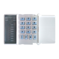
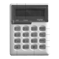
5. Enrolling Keypads and Other Bus-wired Peripherals
Keypads must be enrolled on the system before they can be used. Keypads are allocated an ID in the order in
which they are enrolled. To enrol a keypad:
1. Wire it to the keypad BUS
2. Power the system up
3. Press the [#] key
Repeat this process with the remaining keypads where more than 1 keypad is used. The first keypad enrolled
will have an ID of 1, the second enrolled will have an ID of 2, the third an ID of 3 etc.
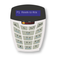
NOTE:
All the zone and LEDs will flash on a keypad that does not have an ID.
The POWER and READY LEDs will be on for a keypad that has an ID and no zone violations.
Only the POWER LED will be on for a keypad that has an ID with a zone violation. The LED for that zone
will also flash.
 Loading...