IDS X-Series Installer Manual 700-398-02H Issued July 2013
8. How to Read Location Values
Values within a data program location will be displayed by the zone LEDs in binary coded decimal format i.e.
zone LEDs 1-4 indicate units (ones) and zone LEDs 5-8 indicate tens (tens), and so on.
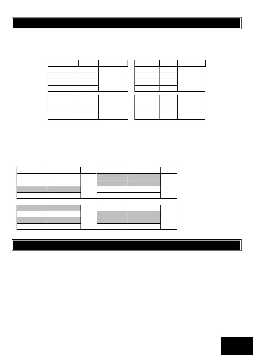
To read a binary value on the keypad, add up the values represented by each lit LED as shown in Table 1
Table 1: Values Represented by each Zone LED
EXAMPLE:
Imagine the following zone LEDs are on: Zone 1, Zone 3 and Zone 5.
Units are represented by the sum of Zone 1 and Zone 3 (i.e. 1 + 4).
Tens of units are represented by the value of Zone 5 (i.e. 1 x ten).
Therefore, the displayed value is (1+4) + (10) = 15.
Values within a time program location are displayed in a similar format as per Table 2.
Table 2: Binary Coded Decimal Four Digit Display
Using an LCD keypad means that data and time information can be read directly without a need to convert.
9. Programming of the Panel
The X-series control panels can be fully programmed using the X-series LED keypad; the system is optimised to
use an LCD keypad. The following section describes how programming data is represented in the X-series
panels and how to program it, specifically with the LED keypad.
For all programming procedures, the [*] key functions as the <ENTER> key and the [#] hash key functions as a
<CLEAR> or an <EXIT> program key.
Invalid data entries are indicated by means of an error beep consisting of 3 short beeps of the keypad buzzer.
There are two location categories:
Standard locations which are single tiered and do not contain any sub-locations.
Extended locations, which are double tiered and have strings or sub-locations depending on the
installers programming preference.
Both standard and extended locations may contain further sub-categories referred to as bitmapped locations.
For both main categories, clear visual keypad prompts are provided, which aid the programming process.
 Loading...