IDS X-Series Installer Manual 700-398-02H Issued July 2013
LOCATIONS 423 – 426 Global Programmable Output Events
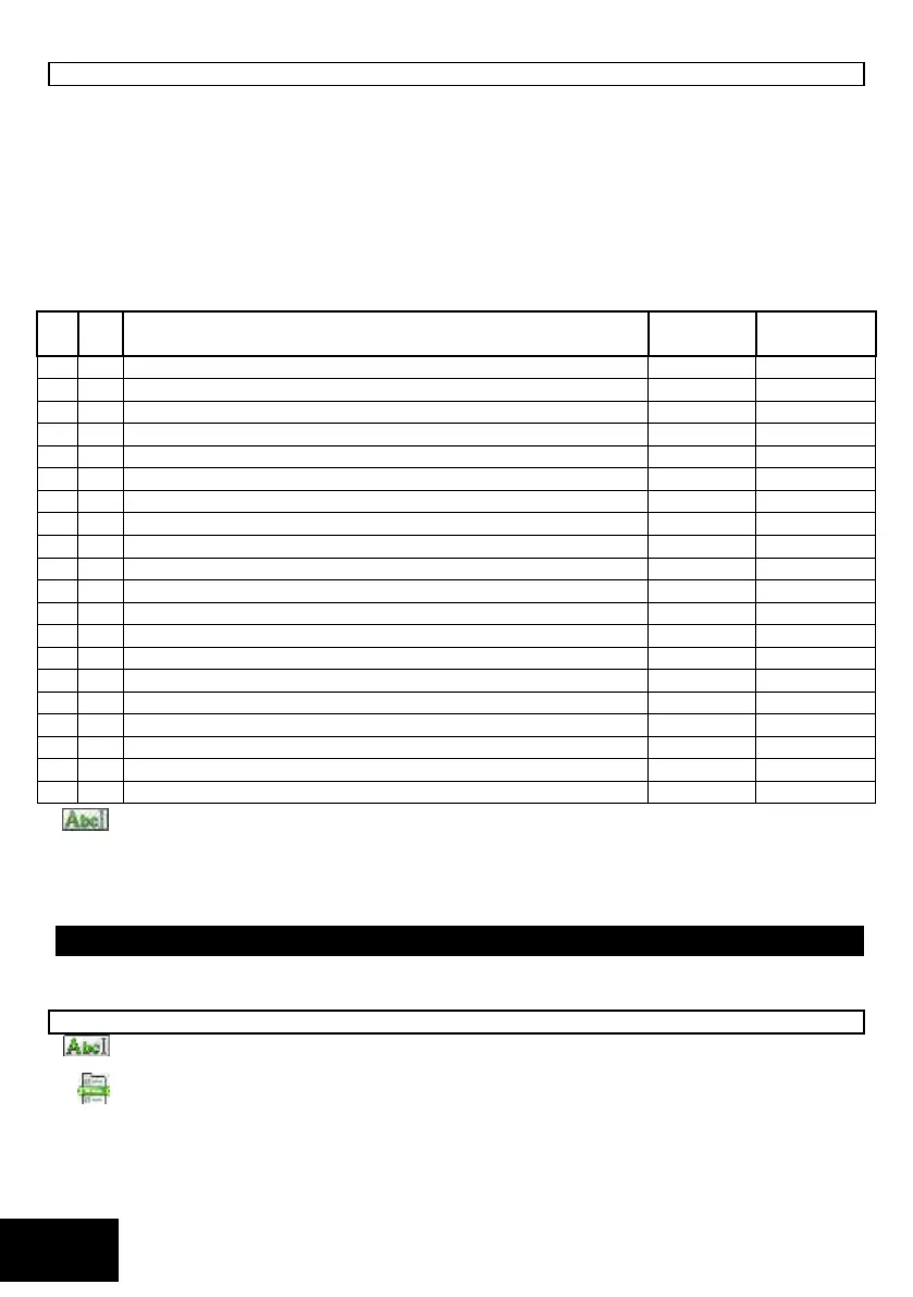
These locations allow you to configure the global programmable output events. Refer to Table 37 to view the
programmable output events per location.
LEDs 1-8 represent the output number, and LEDs 9-16 represent the action. Once a programmable
output has been enabled, the default action will be Pulse High [02].
If dual reporting is enabled, an output allocated to the dual reporting programmable output event will
be set when the panel dials the second phone number, and cleared when it hangs up at the end of the
transmission. This output follows the hook relay. It may be used to trigger switching from the telephone
line to a radio transmitter.
There is no output action for the fire sensor power and dual reporting programmable output events.
Table 37: Global Programmable Output Events Default Data
AC Fail Programmable Output Event
AC Restore Programmable Output Event
Low Battery Programmable Output Event
Low Battery Restore Programmable Output Event
Auto Test Programmable Output Event
Download Programmable Output Event
Siren Tamper Programmable Output Event
Aux 12V Trouble Programmable Output Event
Bus-wired Peripheral Tamper Programmable Output Event
Bus-wired Peripheral Fail Programmable Output Event
Box Tamper Programmable Output Event
Dedicated Panic Programmable Output Event
Communication Fail Programmable Output Event
Telephone Line Tamper Programmable Output Event
Telephone Line Restore Programmable Output Event
Wired Zone Expander Low Battery Programmable Output Event
Wired Zone Expander Low Battery Restore Programmable Output Event
Fire Sensor Power Programmable Output Event
Dual Reporting Programmable Output Event
Enter a 4-digit value (2 digits as per Table 33 and 2 digits as per Table 34 for each programmable
output and program as a 32-digit string, followed by the [*] key.
[INSTALLER CODE] [*] [LOCATION] [*] [SUB-LOCATION] [*] [OUTPUT] [ACTION] [*]
Refer to Using Sub-locations to see how to scroll through sub-location using the [*] key.
NOTE: Once a programmable output has been enabled, the default action will be Pulse High [02].
Output Pulse Timing - Advanced
The following locations determine the length of time for which an output will pulse high before returning to a
clear state.
LOCATION 428 Onboard Output Pulse Time (default = 0002 )
Enter a 4-digit time, [MMSS], for each of the 5 onboard outputs and program as a 20-digit string,
followed by the [*] key.
[INSTALLER CODE] [*] [4] [2] [8] [*] [OUTPUT NO.] [*] [MMSS] [*]
The valid data range is: 00m00s – 59m59s.
Output no. is: 1-5.
 Loading...