IDS X-Series Installer Manual 700-398-02H Issued July 2013
Wireless Integration Options
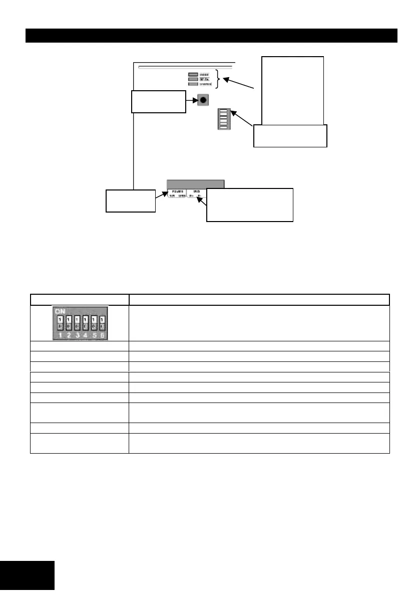
Figure 5: IDS/Duevi Wireless PCB:
DIP switch operation
To address the expander, set the Dipswitches as per table below. Depending on what address is used on the
zone expander, the starting zone number of the expander will be as per table below.
Note: Wireless zones take president over wired zones, if you learn a detector replacing a wired zone; the wired
zone will be ignored. If a detector is allocated to a zone, and the expander corresponding to that zone as
addressed in the table below is not installed, the panel will not communicate with that detector.
Table 29: Dipswitch Configuration Wireless expander
PGM1 will mimic PGM1 output on bus wired expander with the same ID
PGM1 will set on RF Jam, and clear on RF Jam clear for the zones allocated
to the receiver
PGM2 will mimic PGM2 output on bus wired expander with the same ID
PGM2 will set on ANY Supervision fail, and clear on ALL supervisions
restored for the zones allocated to the receiver
Note: Only X64 supports receiver ID 2 to ID 4.
Example:
Zones 1 to 16 have wired zones already installed on them. Now you wish to add another 16 wireless zones
to the system, by making the receiver’s ID 2, all zone on the wireless receiver will be automatically add to
zones 17 to 32.
Defaulting
The second operation is a standalone default feature. If all Dip-switches are ON during power-up then
the unit will default. Please power down after, set appropriate address and power up to resume normal
operation.
 Loading...