PPC-5190 Flat Panel PC
Page 150
The PPC-5190 flat panel PC POS-8520 motherboard comes with a number of peripheral
interface connectors and configuration jumpers listed in Chapter 2. The pinouts for these
connectors are listed below.
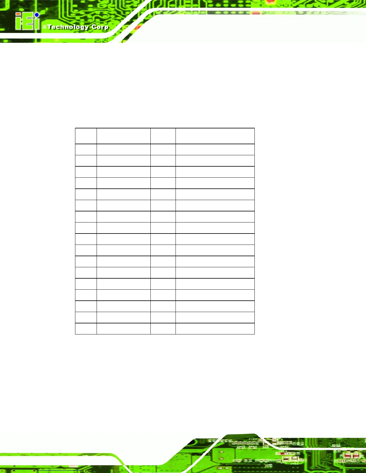
B.1 Floppy Disk Drive Connector
POS-8520 board is equipped with a 34-pin daisy-chain driver connector cable.
PIN Description PIN Description
1 GROUND 2 REDUCE WRITE
3 GROUND 4 N/C
5 GROUND 6 N/C
7 GROUND 8 INDEX#
9 GROUND 10 MOTOR ENABLE A#
11 GROUND 12 DRIVE SELECT B#
13 GROUND 14 DRIVE SELECT A#
15 GROUND 16 MOTOR ENABLE B#
17 GROUND 18 DIRECTION#
19 GROUND 20 STEP#
21 GROUND 22 WRITE DATA#
23 GROUND 24 WRITE GATE#
25 GROUND 26 TRACK 0#
27 GROUND 28 WRITE PROTECT#
29 GROUND 30 READ DATA#
31 GROUND 32 SIDE 1 SELECT#
33 GROUND 34 DISK CHANGE#
 Loading...