PPC-5190 Flat Panel PC
Page 76
Step 2: Detach and remove the elevated platform (see Section 4.3.2).
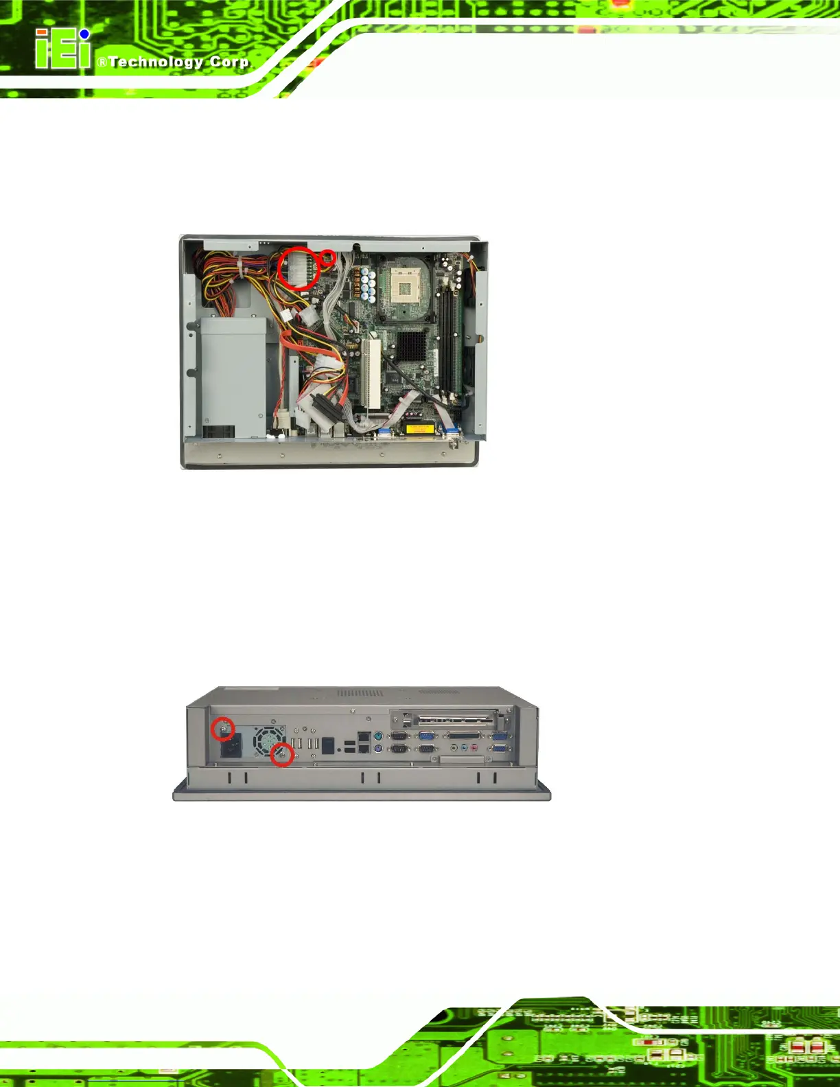
Step 3: Disconnect all PSU connections including those to the motherboard (Figure 4-9)
and any disk drives.
Figure 4-9: PSU Motherboard Connectors
The PSU module is secured to the PPC-5190 flat panel PC with six retention screws, two
connect to the bottom panel (Figure 4-10), two connect to the internal PSU bracket
(Figure 4-12) which is connected to the chassis by two screws (Figure 4-11).
Step 4: Remove the PSU retention screws from the bottom panel (Figure 4-10).
Figure 4-10: PSU Bottom Panel Retention Screws
Step 5: Remove the retention screws that connect the PSU bracket to the chassis
(Figure 4-11).
 Loading...