PPC-5190 Flat Panel PC
Page 73
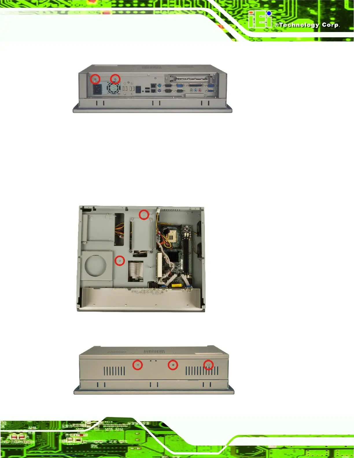
Step 2: Remove the CD drive retention screws from the bottom panel (Figure 4-2).
Figure 4-2: CD Drive Retention Screws
Step 3: The elevated platform is secured to the chassis with twelve retention screws,
two on the internal platform (Figure 4-3), three on the top panel (Figure 4-4),
three on the right panel (Figure 4-5), two on the bottom panel (Figure 4-6) and
two on the PCI riser card (Figure 4-7). Remove the retention screws and lift the
elevated platform out of the chassis. Step 0:
Figure 4-3: Internal Elevated Platform Retention Screws
Figure 4-4: Elevated Platform Retention Screws (Top Panel)
 Loading...