ACCEPTANCE TESTING
7-6 46882/439
RF level frequency response
Test procedure
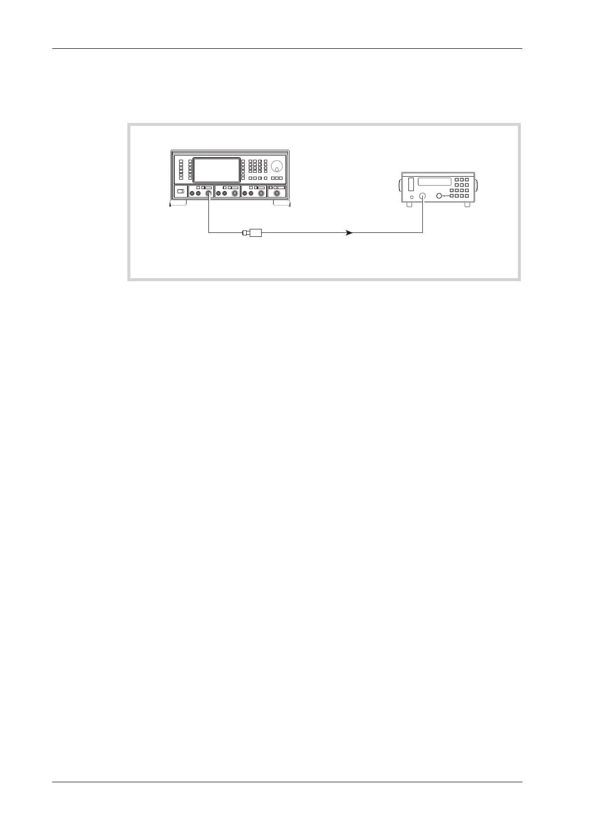
C3491
UUT
6912 or 6932
Power
Sensor
6960B
RF Power Meter
SENSOR
INPUT
RF
OUTPUT
Fig. 7-1 RF output test set-up
(1) Perform AUTO ZERO and AUTO CAL on the power meter.
(2) Connect the test equipment as shown in Fig. 7-1.
(3) On the UUT set source A to:
[Carrier Freq] 30 [kHz]
[RF Level] 0 [dB]
(4) Record the output level measured by the power meter against each of the carrier frequencies
shown in Table 7-1 checking that the results are with
in specification.
(5) Set the UUT RF level to +6 dBm and repeat (4) using Table 7-2.
(6)
Set the UUT RF level to +13 dBm and repeat (4) using Table 7-3.
(7)
Change the 6912 sensor for the 6932 sensor when measuring levels greater than +20 dBm.
Set the UUT RF level to +24 dBm and repeat (4) using Table 7-4.
(8
) Repeat (1) to (7) for source B and, if Option 1 is fitted, source C.
ALC linearity
Test procedure
(1) Perform AUTO ZERO and AUTO CAL on the power meter.
(2) Connect the test equipment as shown in Fig. 7-1.
(3) On the UUT set source A to:
[Carrier Freq] 2.5 [MHz]
[RF Level] −4 [dB]
(4) Record the output level measured by the power meter against each of the steps shown in
Table 7-5 checking that the results are within specification. Change the 6912 sensor for the
6932 sensor when m
easuring levels greater than +20 dBm.
(5) Set the UUT carrier frequency to 500 MHz and repeat (4) using Table 7-6.
(6)
Set the UUT carrier frequency to 2400 MHz and repeat (4) using Table 7-7.
(7
) Repeat (1) to (6) for source B and, if Option 1 is fitted, source C.
 Loading...