115
INSTALLER
USERMAINTENANCE TECHNICIAN
TECHNICAL DATA
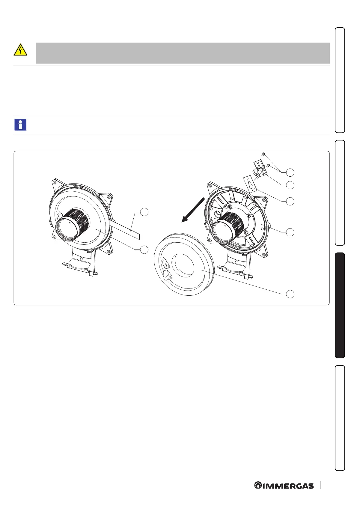
3.24 REPLACING THE MANIFOLD INSULATING PANEL
e operations described below must be performed aer having removed the voltage from the
appliance.
1. To access the inside of the appliance, remove the casing as indicated in Paragr. 3.23.
2. Unscrew the 4 manifold fastening nuts (1, Fig. 91) and gently pull them out towards you at right angles.
3. Unscrew the xing screws (6) of the ignition and detection electrode (5) and remove it.
4. Remove the insulating panel (1) by actuating a blade (2) under its surface.
5. Remove the residue of the xing adhesive from the surface of the manifold (3).
6. Replace the insulating panel (1).
e new insulating panel, used as a spare to replace the removed one, does not need to be xed with glue as its shape with the in-
terference on the burner ensures correct coupling with the manifold.
7. Ret the ignition and detection electrode (5) using the previously removed screws (6) and replace the relative gasket (4).
2
1
1
3
4
5
6
88