18
INSTALLERUSERMAINTENANCE TECHNICIANTECHNICAL DATA
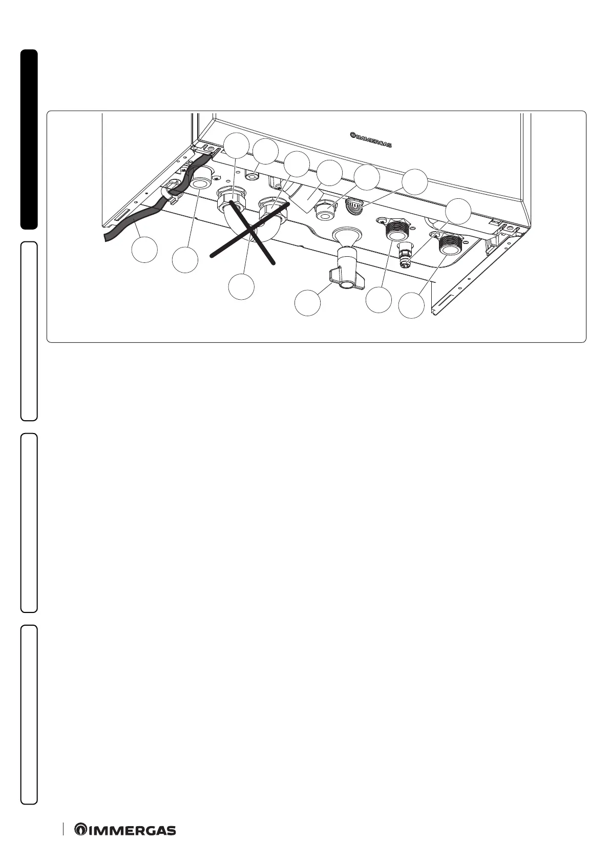
1.6 APPLIANCE CONNECTION UNIT
e connection unit consisting of all the necessary parts to perform the hydraulic and gas system connections of the appliance comes as
optional kit, perform the connections based on the type of installation to be made and according to the layout shown in the gure.
(Fig. 7):
1
2
3
G
V
RU
MU
RR
R
SC
M
4
5
7
e unit includes:
1 - System lling valve knob with screw
2 - System draining valve
3 - 3 bar safety valve drain tting signal
4 - Storage tank unit bypass pipe, to be used only in case of boiler
operating in room heating mode only
5 - Air vent valve drain
Key (Fig. 7):
V - Electrical connection 230V-50Hz
G - 3/4" gas supply
RU - 3/4" storage tank unit return
MU - 3/4" storage tank unit ow
RR - System lling 1/2"
R - 3/4” system return
M - 3/4” System ow
SC - Condensate drain (minimum internal diameter Ø13 mm)