46
INSTALLERUSERMAINTENANCE TECHNICIANTECHNICAL DATA
1.22 CONFIGURATION C
10
C
12
SEPARATOR KIT Ø 80/80
C
10
35
C
12
36
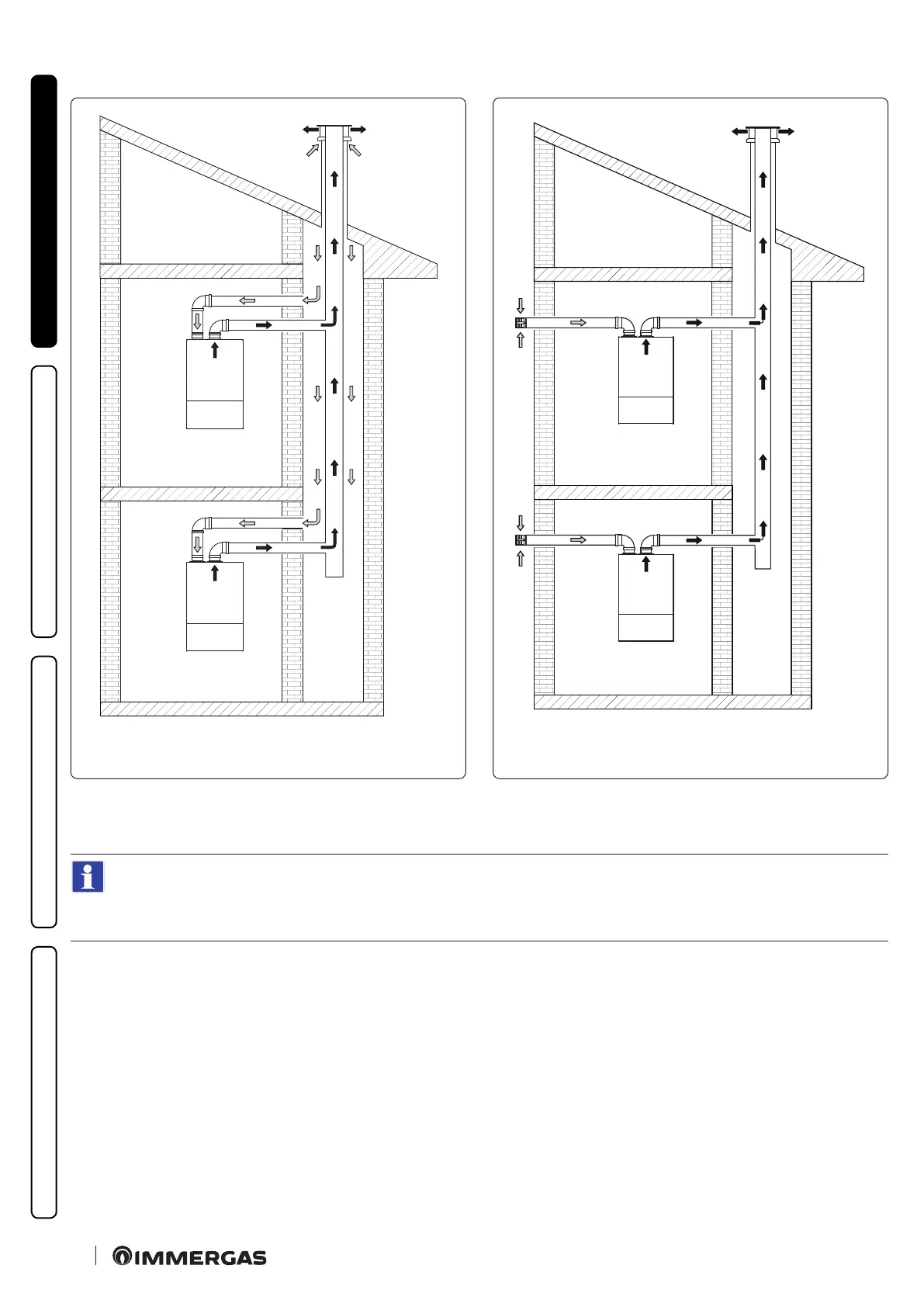
is conguration (allowed only with the approved original ue, including the specic non-return valve), makes it possible to suck the
air outside the home or directly from the sha where the ue gas exhaust is present and the evacuation of the ue gas itself inside a collec-
tive ue.
C
10
(Fig. 35):
Coupling to the sha for intake is possible with male ue Ø 80 or Ø 80 cut female.
C
10
- C
12
(Fig. 35 - 36)
e collective ue coupling for the exhaust is possible with female Ø 80 ue with gasket.
Assembly of separator kit Ø 80/80 (Fig. 37):
1. Install the discharge ange (4) on the appliance sample point ange, positioning the relative gasket (1) with the circular projections
downwards in contact with the appliance ange, and tighten using the hex screws with at tip contained in the kit.
2. Remove the at ange present in the intake hole and replace it with the intake ange (3), positioning the gasket (2) contained in the
separator kit Ø 80/80 and tighten using the supplied self-threading screws.
3. Eliminate the extension Ø 125 from the non-return valve kit on the ue gas.
4. Insert the spacer Ø 80 th. 5 mm into the ue exhaust ange.
5. Insert the ue gas non-return valve on the Ø 80 ues inside the ue exhaust ange.