44
INSTALLERUSERMAINTENANCE TECHNICIANTECHNICAL DATA
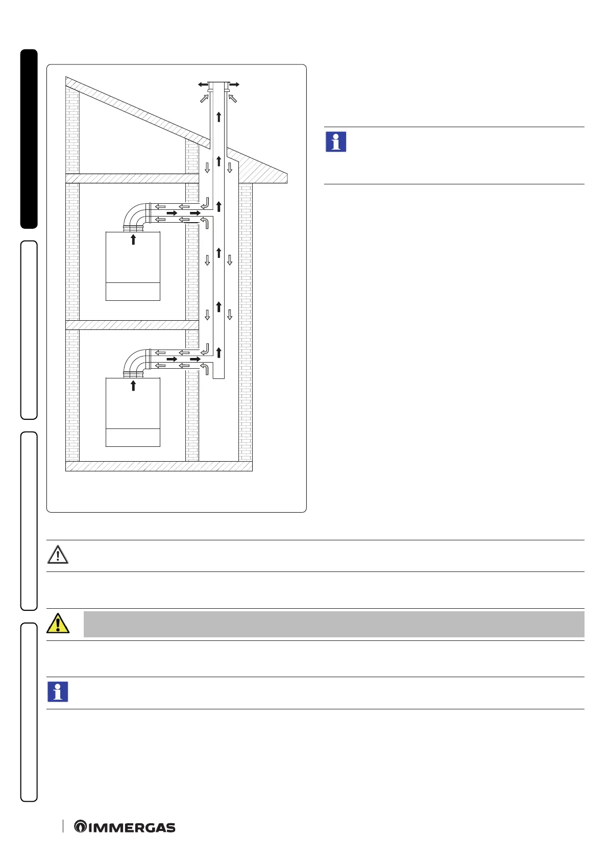
1.21 CONCENTRIC KIT C
10
CONFIGURATION Ø 80/125
C
10
32
Installation in "C
10
" conguration of an Immergas appliance (only
permitted with approved original ue, including the specic
non-return valve), makes it possible to intake combustion air di-
rectly from the sha where the ue gas exhaust is present in the
collective ue.
e connection to the intake sha is possible with a Ø
125 ue.
e collective ue coupling for the exhaust is possible
with female Ø 80 ue with gasket (Fig. 34).
Concentric kit assembly in C
10
type conguration (Fig.34)
To aid in the removal of possible condensate forming in the exhaust pipe, tilt the pipes towards the appliance with a minimum
slope of 5% (Fig.33)
1. Position the anged adaptor (14) interposing the concentric gasket (15) on the appliance, tting it with the screws (13).
2. Insert the non-return valve kit on ue gas Ø80 in the anged adapter, taking care to remove the spacer Ø 80 th. 5 mm.
Make sure to ll the ue gas non-return valve siphon with water (Fig. 40):
3. Fit the Ø 125 extension in the anged adapter.
4. Insert the Ø 80/125 bend on the non-return valve.
For maximum extension of the Ø 80/125 ue and for the installation variables, refer to the gure (Fig. 33).Refer to the relative
tables to calculate the resistance factor (Parag. 1.13).
5. Calculate the distances between the bend and the connection to the collective ue and the sha.
6. Adapt the extension (10), calculating that the inner pipe of the concentric kit must t as far as it will go into the collective ue. e out-
er pipe must engage up to the door.