119
INSTALLER
USERMAINTENANCE TECHNICIAN
TECHNICAL DATA
3.27 SPECIFIC INFORMATION FOR CORRECT APPLIANCE INSTALLATION IN COMMON
PRESSURISED FLUE SYSTEMS C
10
C
12
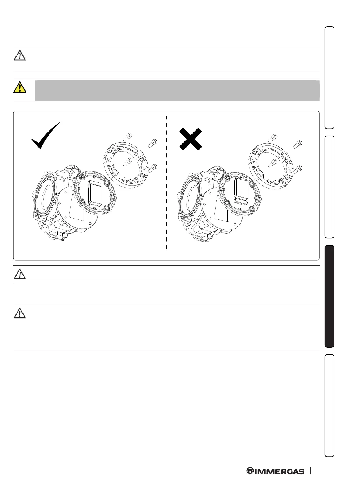
e appliance is factory equipped with a ue gas non-return valve located downstream of the fan, this device, given the impor-
tance of its correct operation, must have its installations C
(10)
and C
(12)
checked on an annual basis, and the active rubber element
must be replaced in case of cuts in the moving parts.
For safety reasons, the ue gas non-return valve (inside the appliance) must be replaced aer
10 years of operation.
92
Before removing the sealing elements of the sealed chamber, using the ue gas analyser and with the appliance o, check that
there are no traces of combustion products in the ue gas sample point.
e presence of combustion products indicates that the non-return valve on the ue gas (in appliance exhaust) is not properly closed, in
which case it is appropriate to check the absence of ue gas even in the sealed chamber (analysis via air sample point).
If malfunctions are detected on the ue gas non-return valves, especially on the discharge valve, in the absence of a shut-o ue
adjusting device at the coupling point of the ue in the pressurised collective ue, it will be necessary to turn o all the boilers
connected to the pressurised collective ue itself, or make sure to intercept the connection point to avoid the dispersion of com-
bustion products into the environment.
Only then proceed to verify the components, making sure that the non-return valve siphon on the ue gas (on the exhaust) (Fig.
40) is full and replacing them if malfunctioning or damaged.