57
INSTALLER
USERMAINTENANCE TECHNICIAN
TECHNICAL DATA
1.32 UPM4 CIRCULATION PUMP
e appliances are supplied with a variable speed circulator pump.
In the central heating mode, the following operating modes are available and can be selected from the "P.C.B. programming" menu (Par.
3.13).
e ∆T can be controlled compatibly with the characteristics of the central heating system and of the appliance.
- Proportional head (A4 = 0): the circulator speed varies according to the power emitted by the burner, the greater the power the great-
er the speed.
- ∆T Constant (A4 = 5 - 25 K): the pump speed varies to maintain the ∆T constant between the system ow and return according to set
value K (A4 = 15 Default).
- Fixed: by setting parameters "A2" and "A3" at the same value (6 - 9), the pump operates at constant speed. For the boiler to work proper-
ly, it is not allowed to drop below the minimum value indicated above.
In domestic hot water mode, the circulator pump always runs at full speed.
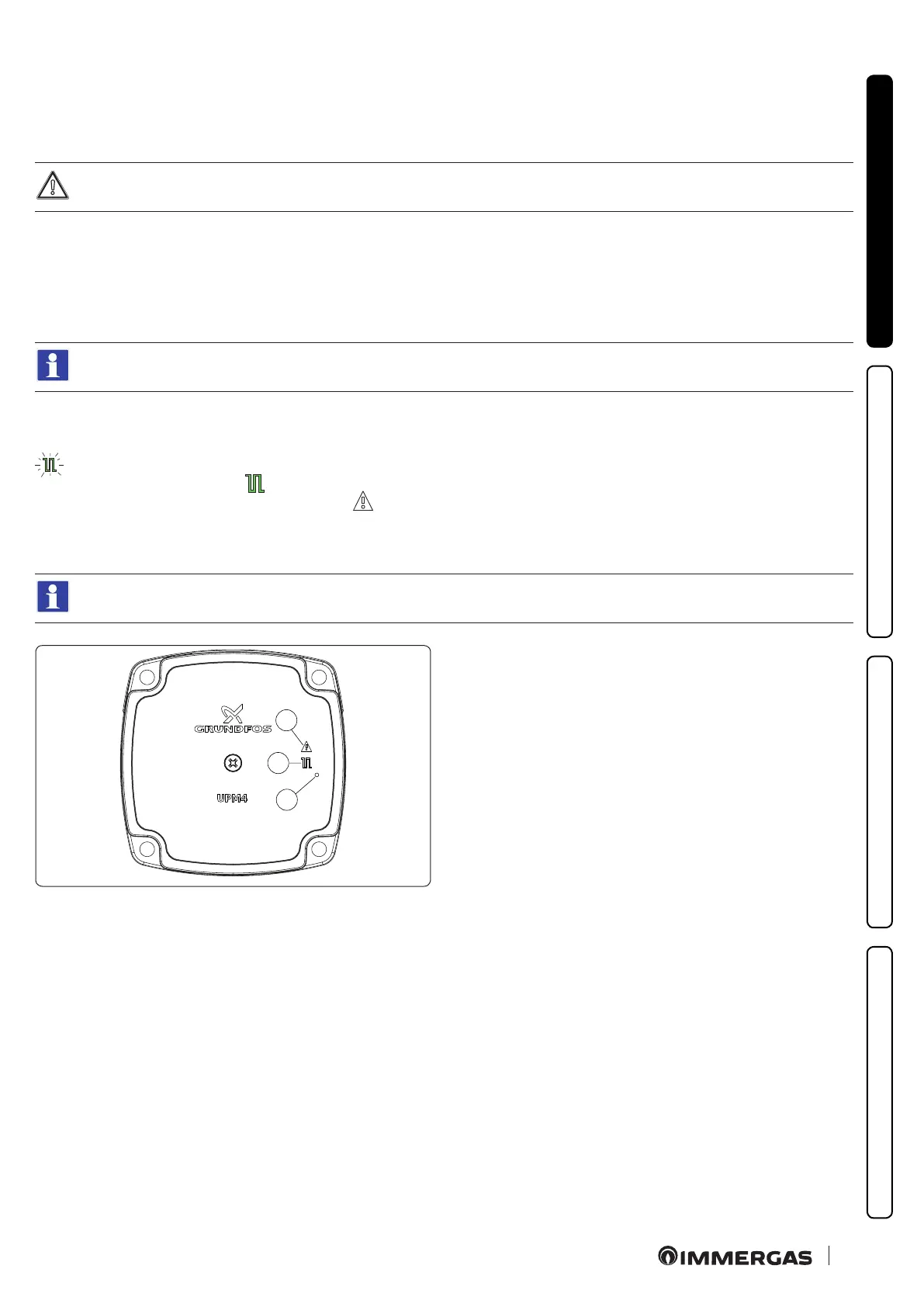
Pump symbols (Fig. 44):
With the pump powered and the pwm control signal connected and operating (pump ON or in stand-by), the symbol 2 ashes green (
).
If the symbol 2 turns steady green ( ), the pump detects no command on the pwm signal and always runs at maximum speed.
If the pump detects an alarm, symbol 1 lights up red ( ). is can mean that there is one of the following faults:
- Low power supply voltage.
- Rotor seized (Cautiously turn the screw in the centre of the head to manually release the motor sha).
- Electrical error.
ese anomalies will be signalled on the boiler display as errors "60" or "61" as indicated in par. 2.5.
2
1
3
44
Key (Fig. 44):
1 - Alarm signal (Red)
2 - Functioning status signal (Steady green/Flashing green)
3 - Led (Not used on this model)