82
INSTALLER
USERMAINTENANCE TECHNICIAN
TECHNICAL DATA
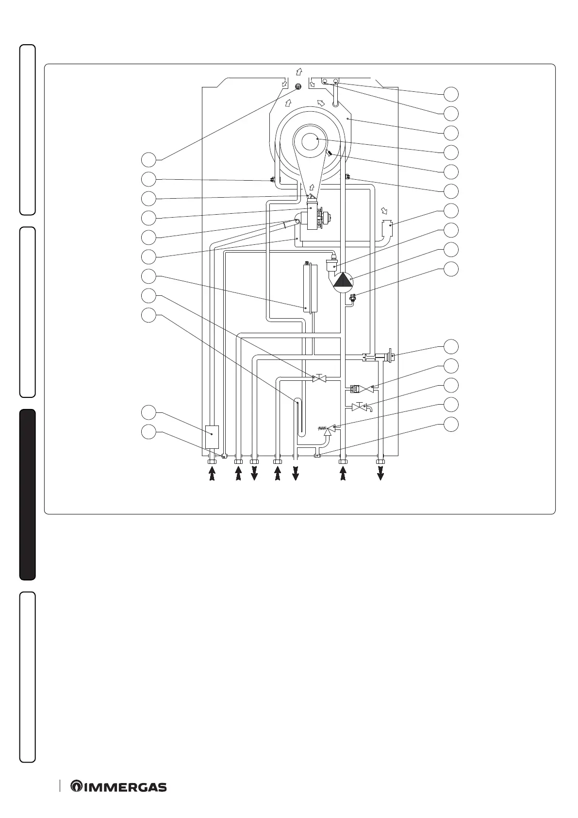
3.4 HYDRAULIC DIAGRAM
M
RR
SC
R
2
3
4
5
6
7
8
9
10
11
1
12
13
14
15
16
17
18
19
20
21
22
26
23
24
25
52
Key (Fig. 52):
1 - Air vent valve drain
2 - Gas valve
3 - Condensate drain trap
4 - System lling valve
5 - System expansion vessel
6 - Air-gas mixer
7 - Gas diaphragm
8 - Fan
9 - Non-return valve on ue gas
10 - Module ow probe
11 - Double ue probe
12 - Flue sample point (F)
13 - Air sample point (A)
14 - Condensation primary exchanger
15 - Burner
16 - Ignition-detection electrode
17 - Return probe
18 - Air intake pipe
19 - Air vent valve
20 - Appliance pump
21 - Pressure transducer
22 - Motorised 3-way valve
23 - By-pass
24 - System draining valve
25 - 3 bar safety valve
26 - 3 bar safety valve drain tting signal
G - Gas supply
RU - Storage tank unit return
MU - Storage tank unit ow
RR - System lling
SC - Condensate drain
M - System ow
R - System return