Thermography System VarioCAM
®
HD
7. Introduction
24 © InfraTec GmbH 2016 User Manual
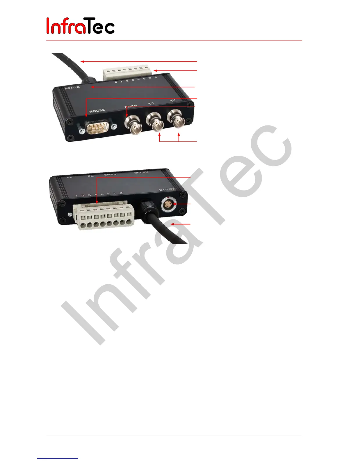
Connecting the breakout box
Fig. 20 Breakout box (trigger; RS232.,BNC)
Fig. 21 Breakout box backside
The terminal strip of the breakout box has the following pin assignments:
■ 1 AOUT1 Analogue output 1
■ 2 AOUT2 Analogue output 2
■ 3 GND Reference potential for AOUTx, I / Ox
■ 4 T1 Trigger 1 / Digital I / O1 (bidirectional)
■ 5 T2 Trigger 2 / Digital I / O 2 (bidirectional)
■ 6 GND Reference potential for AOUTx, Tx
■ 7 PS + Power supply +
■ 8 PS - Supply voltage -
7.9 Trigger functionality VarioCAM
®
HD*
7.9.1 Trigger function
Triggering uses the Ethernet to affect the 16 bit IRB data transmission. The TTL/CMOS signal is
forwarded to the VarioCAM
®
HD (right-hand side socket) using the BNC sockets marked T1 and T2 of the
breakout box and from there using the connecting cable with 14-pin LEMO connector. In order to connect
the trigger signal sources to the breakout box, commercially available BNC cables may be used.
BNC video port (PAL/NTSC-FBAS)
Serial interface (RS232)
Trigger T1, T2 (configurable)
LEMO socket, 14-pin for connection
to the wall plug transformer
Cable for VarioCAM
®
HD head (with 14-
pin LEMO connector)
Terminal strip (analog output)
Connecting the wall plug transformer
to the 14-pin LEMO socket
Connecting cable
Terminal strip