Thermography System VarioCAM
®
HD
8. Introduction
28 © InfraTec GmbH 2016 User Manual
8.2 User interface
8.2.1 Elements of the user interface
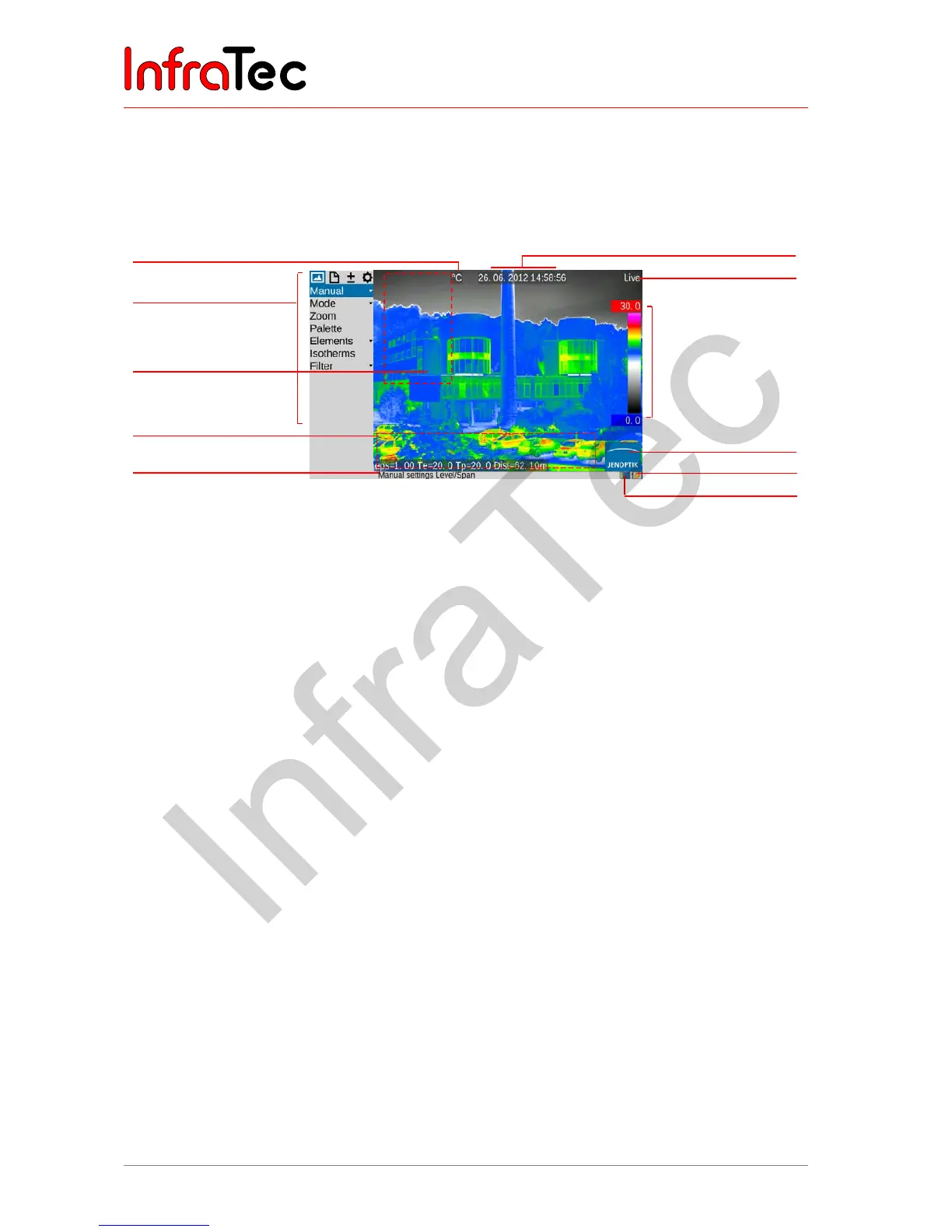
Main image elements
Fig. 24 Arrangement of the image elements
The image elements have the following functions:
■ Image
Central display area Display of the current thermal image, VIS image
or of a superimposition of both images, display of
saved images
■ Menu
Left from screen area Adjustment of the camera functions
■ Help
Lower screen area, left Display of the current function
■ Logo
Lower right corner of the
screen
Manufacturer’s logo
■ Date, time
Screen center, upper edge
of screen
Date and system time
■ Camera status
Upper right corner of the
screen
Current mode of operation
■ Temperature scale
Right edge of the screen Assignment of the colors/shades of grey, of the
image to the temperature range shown
■ Measured values
table
Left screen area Display of temperature values
■ Status symbols
Lower screen area, right Status indicators for
■ Power supply (wall plug transformer/status
rechargeable battery)
■ SDHC-card
■ Laser rangefinder*/laser pointer*
■ Photo LED*
■ GPS reception*
Temperature unit
Camera menu
Field for
measured values table
Information field for
system information
Help line
Date/time
Camera status (mode)
Colour scale with
upper and lower limits
of the shown
temperature range
Logo
Status indications
Rechargeable battery,
SDHC-card