Thermography System VarioCAM
®
HD
9. Introduction
User Manual © InfraTec GmbH 2016 73
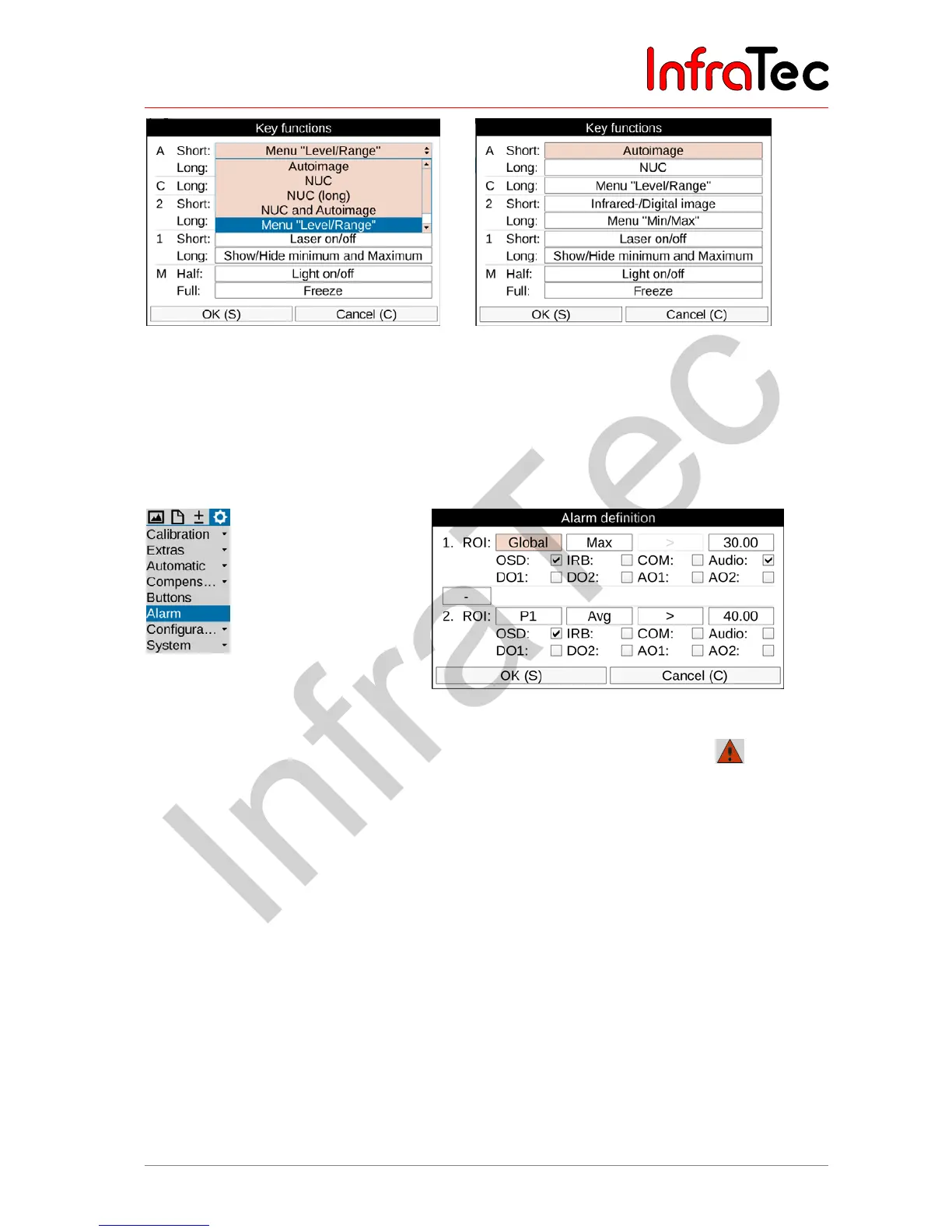
Fig. 170 Button function settings Fig. 171 Button assignment – factory settings
It is possible to assign one function to several buttons at the same time.
9.4.6 Menu item "Alarm"
The "Alarm" menu item can be used in order to define conditions, the fulfillment of which will trigger the
camera to perform actions.
Fig. 172 "Alarm" (Alarm) menu item Fig. 173 Alarm definition settings
The activated alarm function is displayed in the toolbar below the logo with the symbol . The header
in the setting menu 'Alarm Definition' is also shown in red. These displays are made irrespective of
whether an alarm condition is met or not. For two measurement objects (1. ROI and 2. ROI) temperature
thresholds can be defined, that apply to the average (“Avg”), temperature maximum (“Max”) or
temperature minimum (“Min”) of the corresponding measurement object or the overall picture (“Global”).
For each ROI and the corresponding temperature threshold, a comparison is defined: > or <, where for
“max” only > and “Min” only < selectable is.
If these defined conditions are met, the following actions can be performed:
■ OSD Alarm indication on display viewfinder including display of achieved condition
■ IRB Image storage according to setting storage format
■ COM Alarm signaling via RS232 interface *
■ Audio Acoustic alarm signal output
■ DO1 Alarm signal at the digital output 1*
■ DO2 Alarm signal at the digital output 2*
■ AO1 Alarm signal at the analogue output 1*
■ AO2 Alarm signal at the analogue output 2*