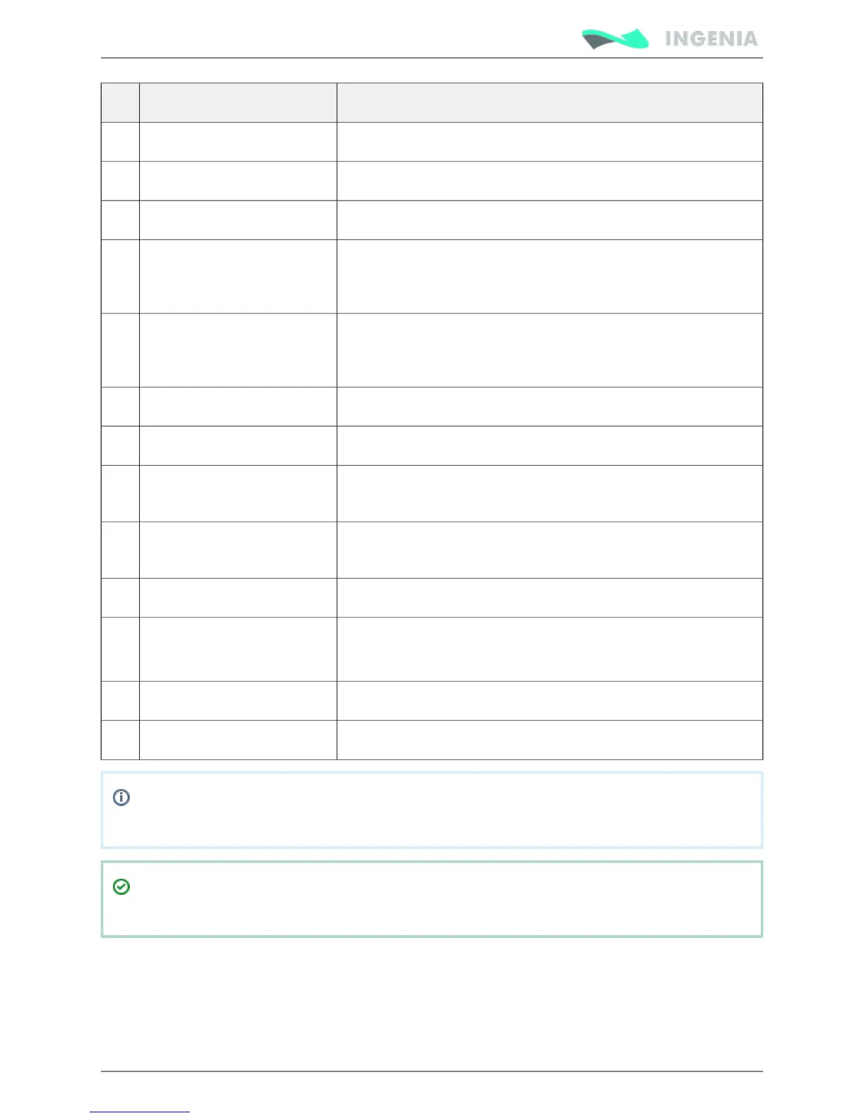
Pin Name Description
4 GPO2 Digital output 2
5 GPO1 Digital output 1
6 GND Ground
7 HS_GPI1+ / PULSE+ / PWM+ High speed digital differential input 1+
Command source: Pulse+ input
Feedbacks: PWM+ input
8 HS_GPI1- / PULSE- / PWM- High speed digital differential input 1-
Command source: Pulse- input
Feedbacks: PWM- input
9 GND Ground
10 AN_IN1 Single ended analog input 1
11 AN_IN2- Differential analog inverting input 2
Single ended analog input 2 ground
12 AN_IN2+ Differential analog non inverting input 2
Single ended analog input 2
13 GND Ground
14 LS_GPI2 Low speed digital single ended input 2
(Could be safe torque off input on request, please contact us)
15 LS_GPI1 Low speed digital single ended input 1
16 +5V_EXT +5V 200mA max output (shared with feedback connector)
Note: In previous Pluto versions (1.0.1R) which had CLIK-Mate connectors this pin was connected
to GND. Please see for more information.Hardware revisions
I/O connector pinout is shared with , , and servo drives, which allows Nix Jupiter Hydra Neptune
using the with Pluto.IO starter kit
Supply and shunt connector
The supply and shunt connector is a 3 pin pluggable terminal block with 3.5 mm pitch. See Power supply
for power wiring information. Details on shunt operation see .wiring External Shunt Resistor
Pin numbers and connectors pinout are shown below: