Signalling LEDs
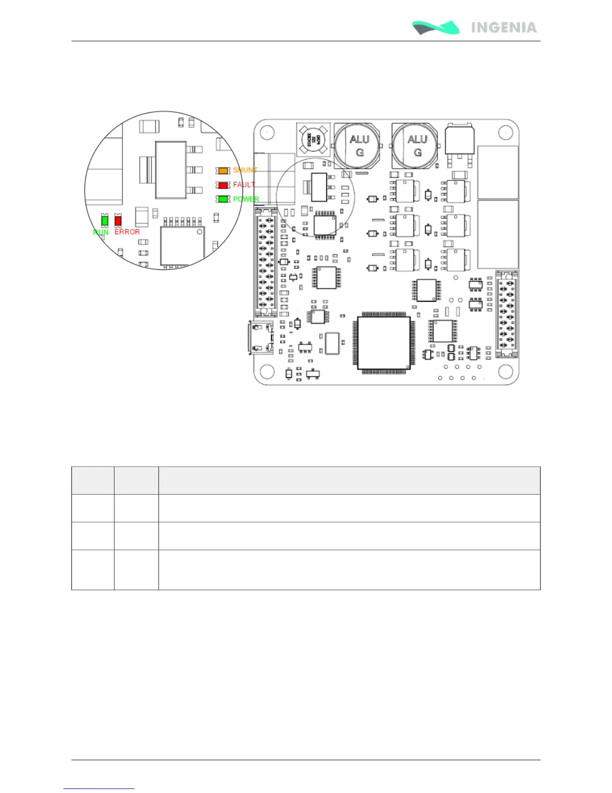
Pluto Servo Drive has 5 signalling LEDs near the CAN interface connector and USB connector.
Power and motor signalling LEDs
Next table shows the meaning of each motor and power LED.
LED Colour Meaning
POWER Green LED is on when internal power supply is working.
FAULT Red LED is on when a has occurred.fault or error
SHUNT Orange LED is turned on with the Shunt PWM signal and indicates that maximum user
voltage has been exceeded and Shunt is enabled.
CAN signalling LEDs
There are 2 LEDs besides the CAN interface connector. These LEDs provide information regarding
communication status according to CANopen . The Red LED is and CiA 303-3 recommendations ERROR LED
green one is .RUN LED
The CANopen ERROR LED indicates the status of the CAN physical layer and errors due to missing CAN
messages (sync, guard or heartbeat). Next table shows the CANopen ERROR LED truth table: