The encoder broken wire detection only works when the encoder is . configured as differential
An will be generated if the encoder is disconnected or some wire is broken.error
To avoid a broken wire fault if the differential encoder has no index (Z) line, connect the negative
pin (ENC_Z-) to GND (this ensures the XOR result = 1) or configure the encoder as single ended in
MotionLab.
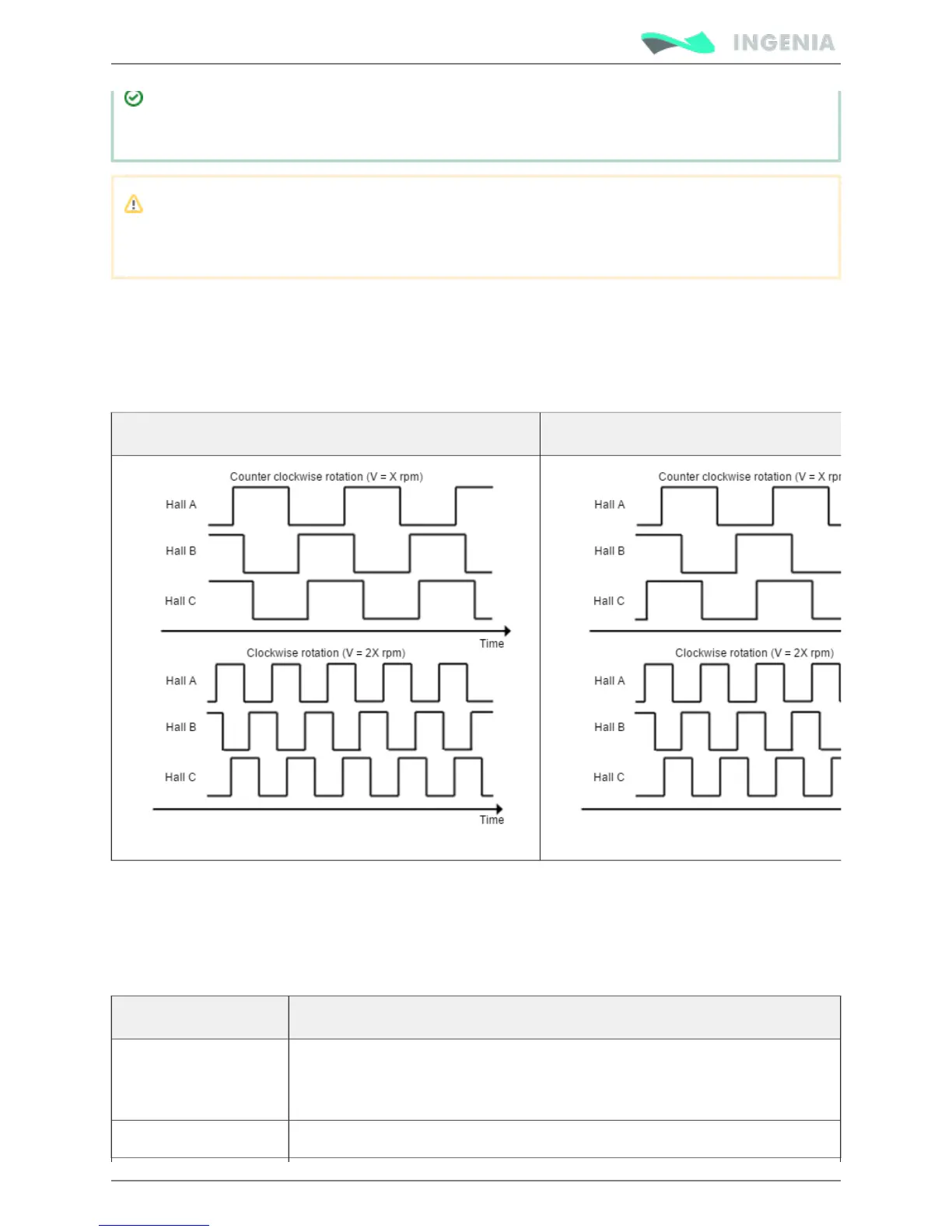
Digital Halls interface
The Hall sensors are Hall effect devices that are built into the motor to detect the position of the rotor
magnetic field. Usually, motors include 3 hall sensors, spaced 60º or 120º apart. Using these 3 signals, the
drive is capable to detect the position, direction and velocity of the rotor. Next figures show examples of
digital halls signals.
Digital halls signals example (60º option) Digital halls signals example (120º option)
Digital halls can be used for commutation, position and velocity control. Resolution using these sensors is
much lower than using encoders. Pluto can use single ended Hall sensors to drive the motor with
trapezoidal commutation, but not with sinusoidal commutation.
This interface accepts 0-5 V level input signals. Inputs are pulled up to 5 V, so industry standard open
collector and logic output hall effect sensors can be connected. Next table summarizes digital halls inputs
main features:
Specification Value
Type of inputs Non-isolated
Single ended with pull-up and low pass filter
ESD protected