1.
2.
3.
Refer to for more information about connections and wires. Refer to Feedback wiring recommendations
for more information about High Speed digital inputs.High-speed (HS) digital inputs interface
PWM encoder wiring should be physically isolated from motor, AC power and all other power
wiring.
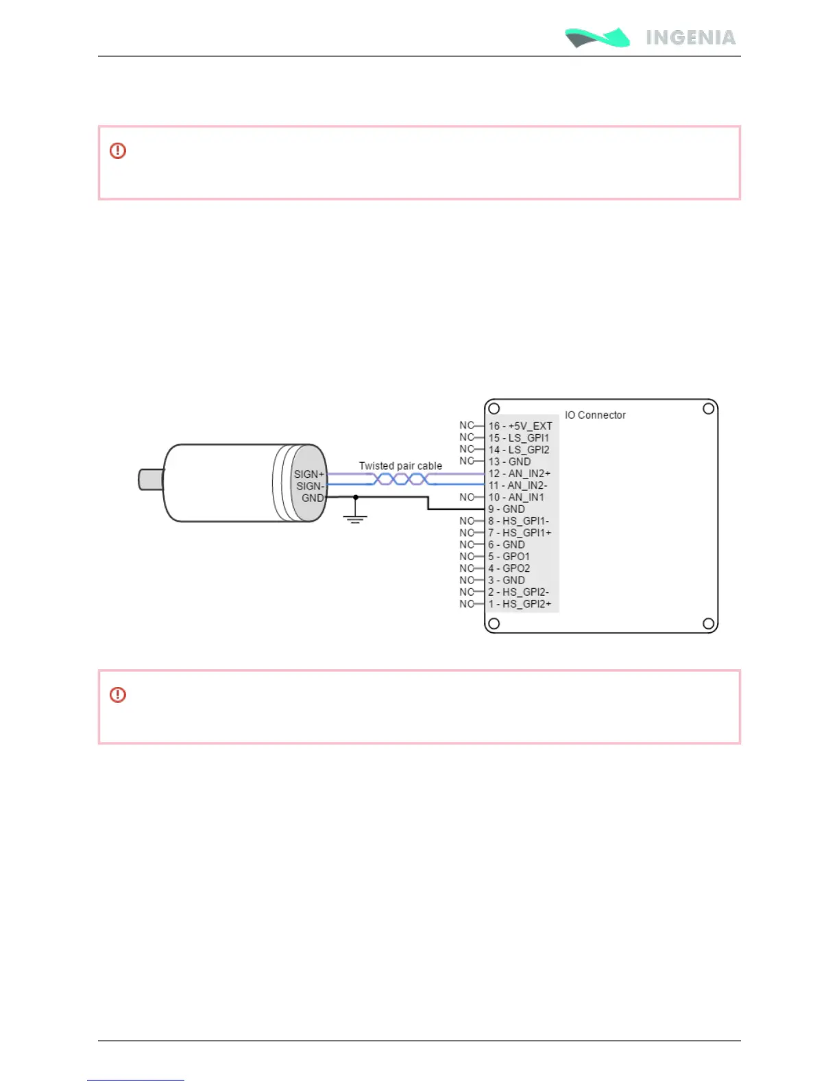
DC tachometer
The Pluto Servo Drive can use a DC tachometer signal as velocity feedback element. Tachometer provides
an analog signal whose voltage level is proportional to the rotor speed.
There are two analog inputs with different input voltage range. Any of them can be used as velocity
feedback input, and can be selected via software depending on the voltage range of the feedback element
and its kind of output (single ended or differential).
Next figure illustrates how to connect source tachometer to the Pluto Servo Drive for differential sources.
DC tachometer feedback wiring should be physically isolated from motor, AC power and all other
power wiring.
Feedback wiring recommendations
The most frequent problems encountered in transmitting feedbacks signals to the receiving electronics
are signal distortion and electrical noise. Either problem can result in gain or loss of counts for digital
feedbacks or bad voltage levels for analog ones. To minimize these problems there are some essential
good wiring practices that should followed:
Always connect both positive and negative signals when using differential digital encoders, Hall
sensors, PWM encoders or analog feedbacks. Use one twisted pair for each differential group of
signals and another twisted pair for the 5 V supply and GND.
Keep the ground connection between an encoder and the Pluto Servo Drive even if the encoder
supply is not provided by the drive. In very noisy environments, connect the cable shield to the
connector shield only at one side. Never use the shield as a conductor carrying a signal, for example
as a ground line.