Specification Value
Receiver input hysteresis 25 mV (V + V = 0)
+ -
Max frequency 10 MHz
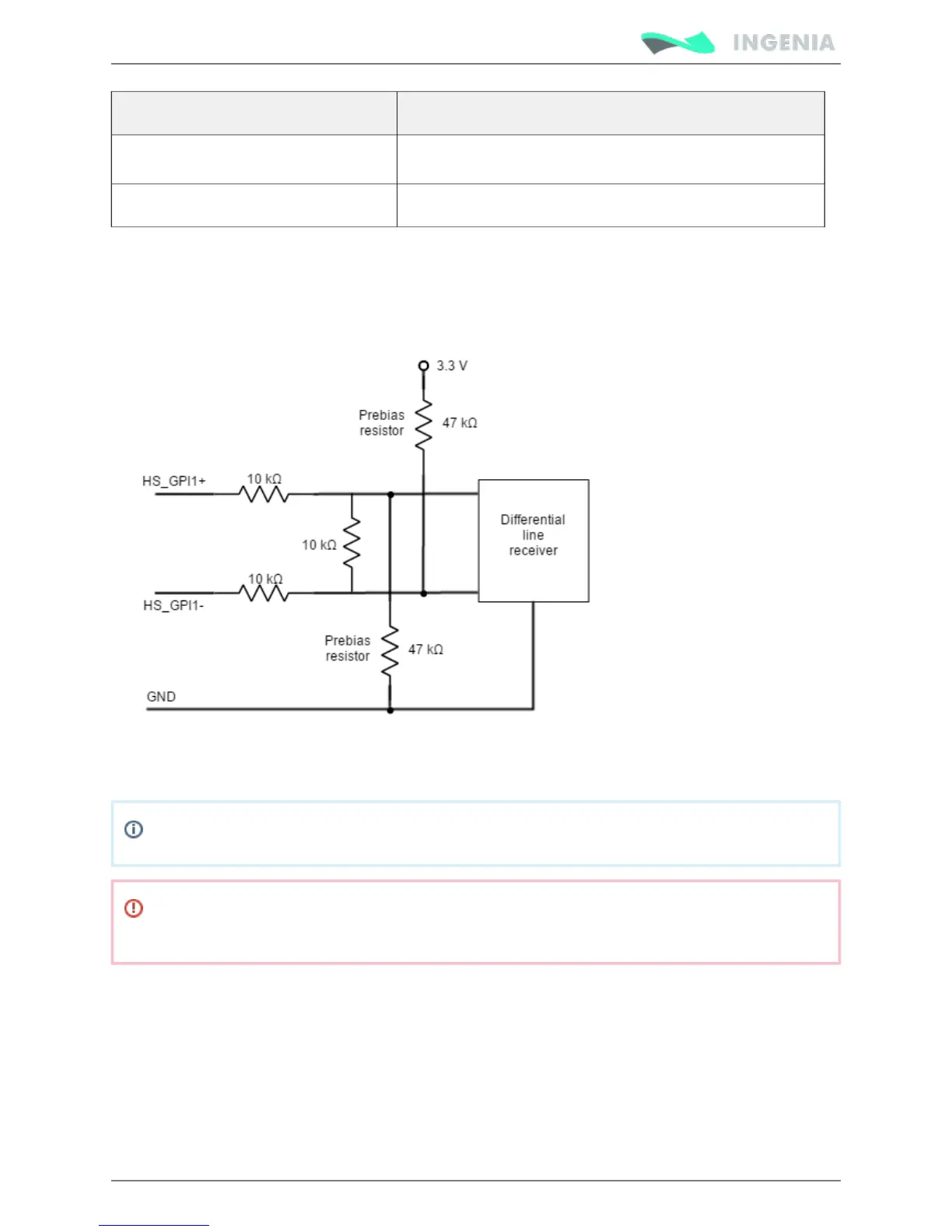
Next figures show the circuit model for high speed digital input. Resistance values are 10 kΩ which results
on a 30 kΩ input impedance. This bias resistor configuration allows single ended and differential input. If
lower impedance is desired to improve noise immunity, a termination resistor can be placed between
HS_GPI+ and HS_GPI-.
Next figure shows an example on how to connect differential sources to these inputs:
For these inputs work as single ended, tie HS_GPIx- to GND, and connect the input signal to the positive
HS_GPI+ input.
HS_GPI1+ and HS_GPI2+ inputs are in LOW state by defect.
Pluto Inputs and outputs are not isolated. The ground of the Pluto Servo Drive and the ground of
the devices connected to I/Os must be the same. Otherwise inputs or outputs may be damaged.
For a high speed signal connection (such as ) to these inputs, refer to next figure Step and Direction
(HS_GPI2 can also be used):