Appendix C
-
161
-
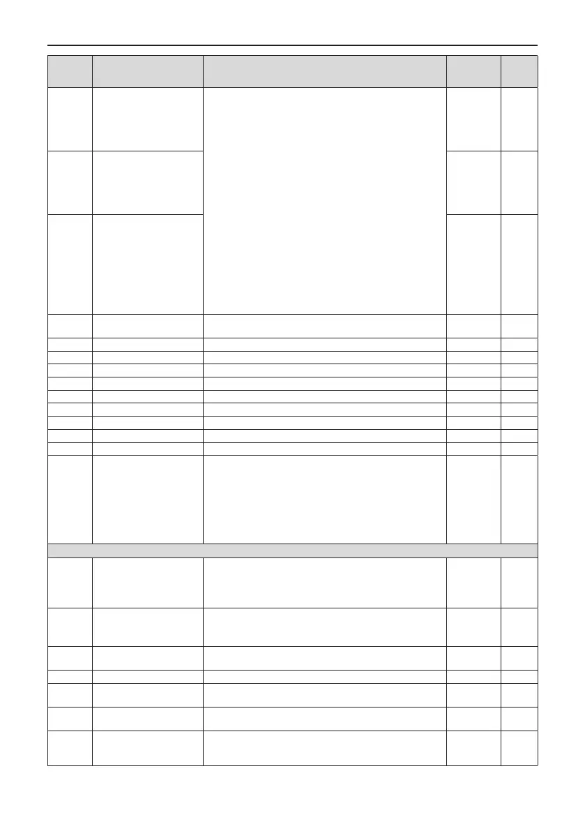
Function
Code
Name Setting Range Default Change
F5-06 FMP function selection
0: Running frequency
1: Set frequency
2: Output current
3: Output torque (absolute value, proportion to motor
torque)
4: Output power
5: Output voltage
6: Pulse input (100.0% corresponds to 100.0kHz)
7: AI1
8: AI2
9: AI3 (extension card)
10: Length
11: Count value
12: Communication setting
13: Motor rotational speed
14: Output current (100.0% corresponds to1000.0A)
15: Output voltage (100.0% corresponds to1000.0V)
16: Output torque (actual value, proportion to motor torque)
0
☆
F5-07 AO1 function selection 0
☆
F5-08 AO2 function selection 1
☆
F5-09
Max. FMP output
frequency
0.01kHz to 100.00kHz 50.00kHz
☆
F5-10 AO1 zero offset coefcient -100.0% to +100.0% 0.0%
☆
F5-11 AO1 gain -10.00 to +10.00 1.00
☆
F5-12 AO2 zero offset coefcient -100.0% to +100.0% 0.0%
☆
F5-13 AO2 gain -10.00 to +10.00 1.00
☆
F5-17 FMR output delay 0.0s to 3600.0s 0.0s
☆
F5-18 Relay 1 output delay 0.0s to 3600.0s 0.0s
☆
F5-19 Relay 2 output delay 0.0s to 3600.0s 0.0s
☆
F5-20 DO1 output delay 0.0s to 3600.0s 0.0s
☆
F5-21 DO2 output delay 0.0s to 3600.0s 0.0s
☆
F5-22
Active mode selection of
DO output terminals
0: Positive logic active
1: Negative logic active
Units position: FMR active mode
Tens position: Relay1 active mode
Hundreds position: Relay2 active mode
Thousands position: DO1 active mode
Ten thousands position: DO2 active mode
00000
☆
Group F6: Start/Stop Control
F6-00 Start mode
0: Direct start
1: Catching a spinning motor
2: Pre-excited start (Ac asynchronous drive)
3: SVC quick start
0
☆
F6-01
Mode of catching a
spinning motor
0: From stop frequency
1: From power frequency
2: From max. frequency
0
★
F6-02
Speed of catching a
spinning motor
1 to 100 20
☆
F6-03 Start frequency 0.00 Hz to 10.00 Hz 0.00 Hz
☆
F6-04
Start frequency holding
time
0.0s to 100.0s 0.0s
★
F6-05
DC injection braking level/
Pre-excitation level
0% to 100% 50%
★
F6-06
DC injection braking
active time/Pre-excitation
active time
0.0s to 100.0s 0.0s
★

 Loading...