3 Installation and Wiring
-
29
-
3
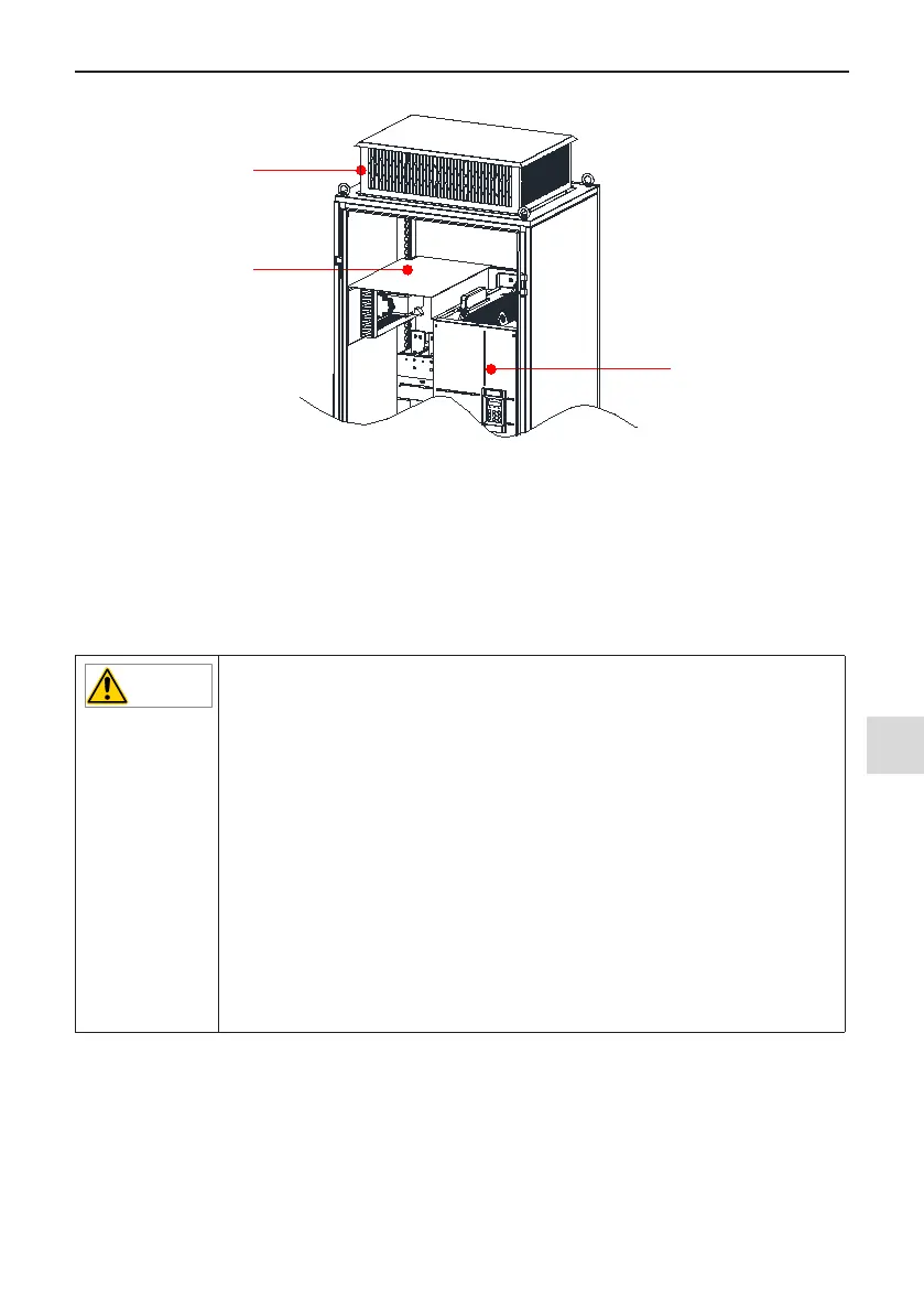
As shown in Figure 3-13, an insulation barrier is required to prevent hot air circulating inside the cabinet.
Cabinet
ventilation top
cover
MD500
Insulation
barrier
Figure 3-13 Insulation barrier in the cabinet
2. Precautions
A nine-folding AL cabinet (PS cabinet) is recommended for installation of the drive. Before installing the AC
drive, check whether xing beams with xing holes are mounted to the cabinet back correctly. Then prepare
the bottom mounting bracket and guide rail (for mounting position and dimensions, see Section 8.2.5). Reserve
sufcient space at the bottom of the cabinet for connecting the side entry terminal.
You can push the AC drive into the cabinet or pull it out of the cabinet after moving the drive onto the guide rail.
Make sure to align the castors to the guide rail and arrange two persons for drive push-in and pull-out to ensure
safety.
◆
Refer to Figure 3-3 for mounting clearance requirements. Ensure there is sufcient
space allowing for efcient heat dissipation of the drive and the other devices in the
cabinet, as shown in Figure 3-11 and Figure 3-12.
◆
Use an extended rod sleeve to operate on the copper terminal of power lines in the
main circuit.
◆
Make sure to align the castors to the guide rail and arrange two persons for drive
push-in and pull-out to ensure safety, as shown in Figure 3-20 and Figure 3-21.
◆
Refer to Figure 3-14 for cabinet layout before mounting the drive in cabinet. The
cabinet dimension is 2200 x 800 x 600 mm. The height 2200 mm includes the 200
mm cabinet ventilation top cover but does not include the 100 mm cabinet base.
Insulation barrier must be installed at the top of the cabinet to avoid circulation of
ventilation airow within the carbinet. In addition, ensure there are air inlet open-
ings at the bottom of the cabinet.
◆
For dimensions of the mounting bracket (delivered with the drive), refer to Section
8.2. The guide rail must have enough strength and stiffness.
◆
After push-in, remove the bafe on the top of the drive, to prevent overheat be-
cause ventilation air cannot ow out.

 Loading...