3 Installation and Wiring
-
32
-
3
■
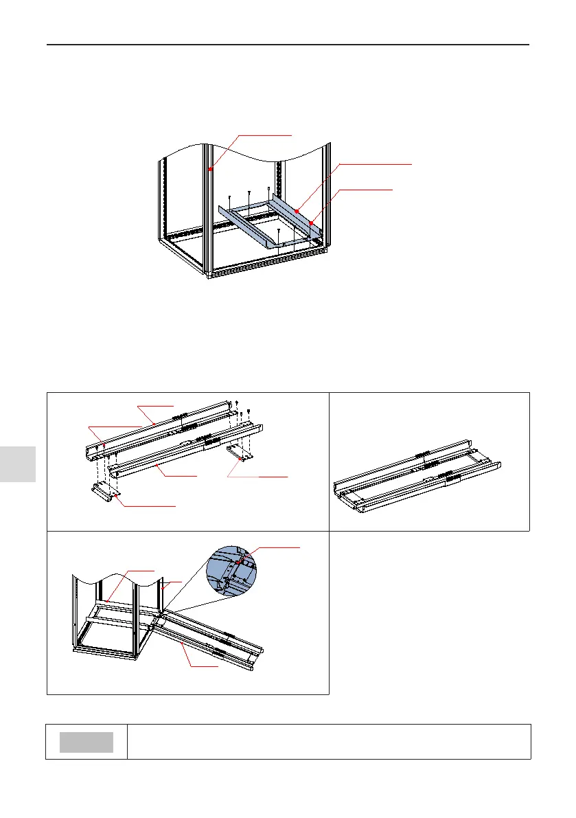
Fix the bottom mounting bracket
●
Use six M5 tapping screws to x the mounting bracket on the nine-folding AL cabinet according to the fol-
lowing gure (the mounting bracket drawing is shown in 8.2.5).
●
If a non-nine-folding AL cabinet is used, drill mounting holes for the mounting bracket on site.
Nine
-folding
AL cabinet
M5 self
-tapping
screw
Quantity: 6 PCS
Bottom mounting bracket
(standard configuration)
Figure 3-17 Installing the bottom mounting bracket
■
Assemble the guide rail (model: MD500-AZJ-A3T10, optional)
As shown in Figure A, assemble the guide rail of correct model. The assembled guide rail is shown in Figure B.
As shown in Figure C, align the two holes at the front of the guide rail with the studs of the mounting bracket,
and x them with two M6 nuts.
M5 x 12 combined
screws (8PCS)
Connecting plate (above
)
Left rail
Right rail
Connecting plate (below)
A Before guide rail assembly B After guide rail assembly
Cabinet
Mounting
bracket
Guide rail
M6 nut (2PCS)
C Assembled guide rail
Figure 3-18 Assembling the guide rail in the cabinet
● Carefully read 19010353 MD500-AZJ-A3T10 Guide Rail Assembly Instructions before
assembling the guide rail.

 Loading...