I/O Subsystem
R
114 Intel
®
815 Chipset Platform Design Guide
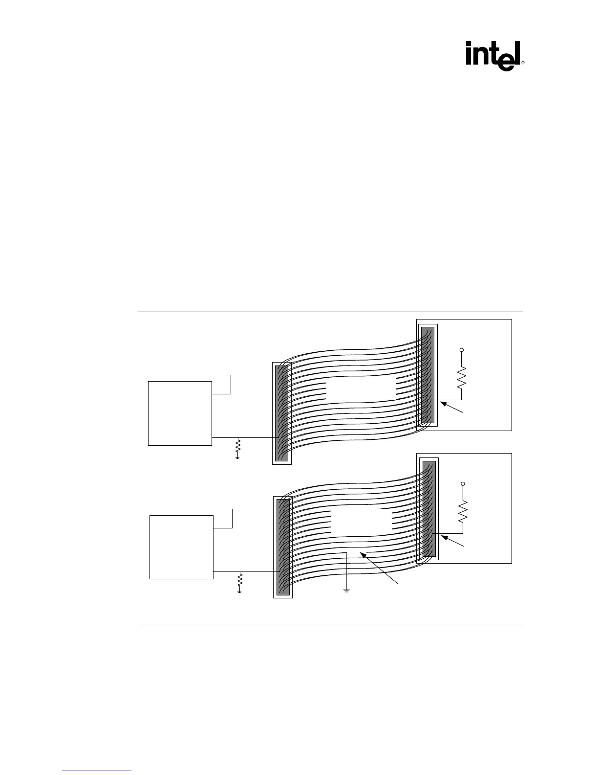
10.2.1 Host Side Cable Detection
BIOS Detects Cable Type Using GPIOs
Host-side detection requires the use of two GPI pins (one per IDE controller). The proper way to
connect the PDIAG#/CBLID# signal of the IDE connector to the host is shown in Figure 58. All
Ultra ATA/66 devices have a 10 kΩ pull-up resistor to 5V. Most GPIO pins on the ICH and all
GPIs on the FWH are not 5V tolerant. This requires a resistor divider so that 5V will not be driven
to the ICH or FWH pins. The proper value of the series resistor is 15 kΩ (as shown in the
following figure). This creates a 10 kΩ/15 kΩ resistor divider and will produce approximately 3V
for a logic high. This mechanism allows the host to sample PDIAG#/CBLID#, after diagnostics. If
PDIAG#/CBLIB# is high, then there is 40-conductor cable in the system and ATA modes 3 and 4
should not be enabled. If PDIAG#/CBLID# is low, then there is an 80-conductor cable in the
system.
Figure 58. Host-Side IDE Cable Detection
80-conductor
IDE cable
IDE Drive
10 k
Ω
5 V
PDIAG
ICH
GPIO
GPIO
To secondary
IDE connector
Open
15 k
Ω
40-conductor
cable
IDE Drive
10 k
Ω
5 V
PDIAG
ICH
GPIO
GPIO
To secondary
IDE connector
15 k
Ω
IDE_cable_det_host