Component Quadrant Layouts
R
Intel
®
815 Chipset Platform Design Guide 27
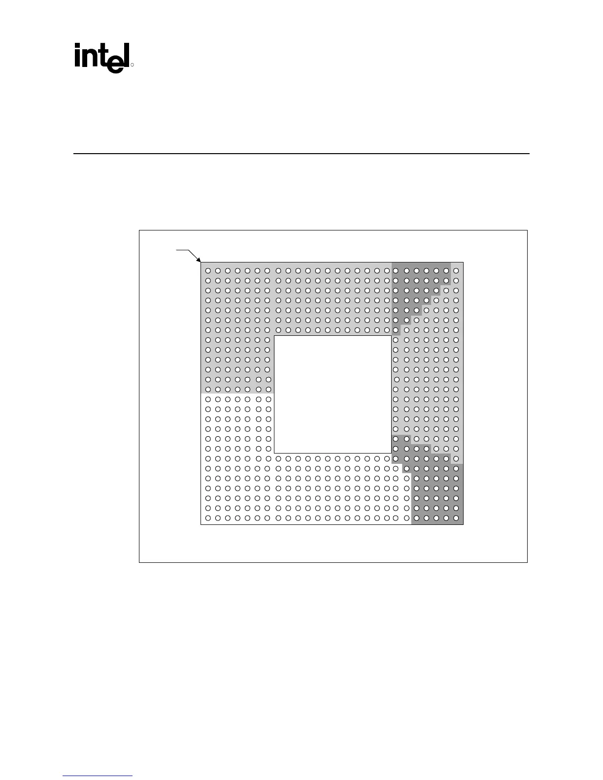
3 Component Quadrant Layouts
Figure 4 illustrates the relative signal quadrant locations on the GMCH ballout. It does not
represent the actual ballout. Refer to the Intel
®
815 Chipset Family: 82815 Graphics and Memory
Controller Hub (GMCH) for use with the Universal Socket 370 Datasheet for the actual ballout.
Figure 4. GMCH 544-Ball µ
µµ
µBGA* CSP Quadrant Layout (Top View)
quad_GMCH
GMCH
System Memory
AGP / Display
Cache
Video
Hub Interface
System Bus
Pin 1
corner