System Bus Design Guidelines
R
60 Intel
®
815 Chipset Platform Design Guide
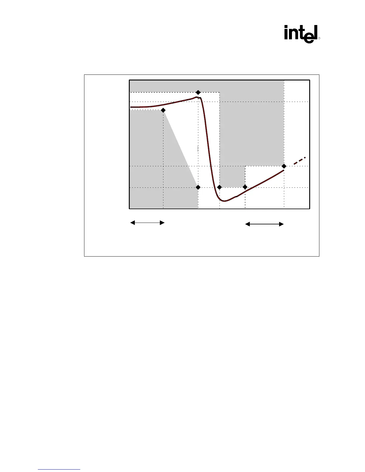
Figure 26. Filter Specification
0dB
-28dB
-34dB
0.2dB
-0.5 dB
1 MHz 66 MHz fcorefpeak1HzDC
passband
high frequency
band
filter_spec
Forbidden
Zone
Forbidden
Zone
NOTES:
1. Diagram not to scale.
2. No specification for frequencies beyond fcore.
3. fpeak should be less than 0.05 MHz.
Other requirements:
• Use shielded-type inductor to minimize magnetic pickup.
• Filter should support DC current > 30 mA.
• DC voltage drop from VCC to PLL1 should be < 60 mV, which in practice implies series
R < 2 Ω. This also means pass-band (from DC to 1 Hz) attenuation < 0.5 dB for
VCC = 1.1V, and < 0.35 dB for VCC = 1.5V.