System Design Checklist
R
Intel
®
815 Chipset Platform Design Guide 169
13.10.1 Power
Checklist
Items
Recommendations
V_CPU_IO[1:0] • The power pins should be connected to the proper power plane for the processor ‘s
CMOS compatibility signals. Use one 0.1
µF decoupling capacitor.
VCCRTC • No clear CMOS jumper on VCCRTC. Use a jumper on RTCRST# or a GPI, or use a
safemode strapping for Clear CMOS
VCC3.3 • Requires six 0.1 µF decoupling capacitors
VCCSus3.3 • Requires one 0.1 µF decoupling capacitor.
VCC1.85 • Requires two 0.1 µF decoupling capacitors.
VCCSus1.85 • Requires one 0.1 µF decoupling capacitor.
5V_REF SUS • Requires one 0.1 µF decoupling capacitor.
• V5REF_SUS only affects 5V-tolerance for USB OC[3:0] ins and can be connected to
VCCSUS3_3 if 5V tolerance on these signal is not required.
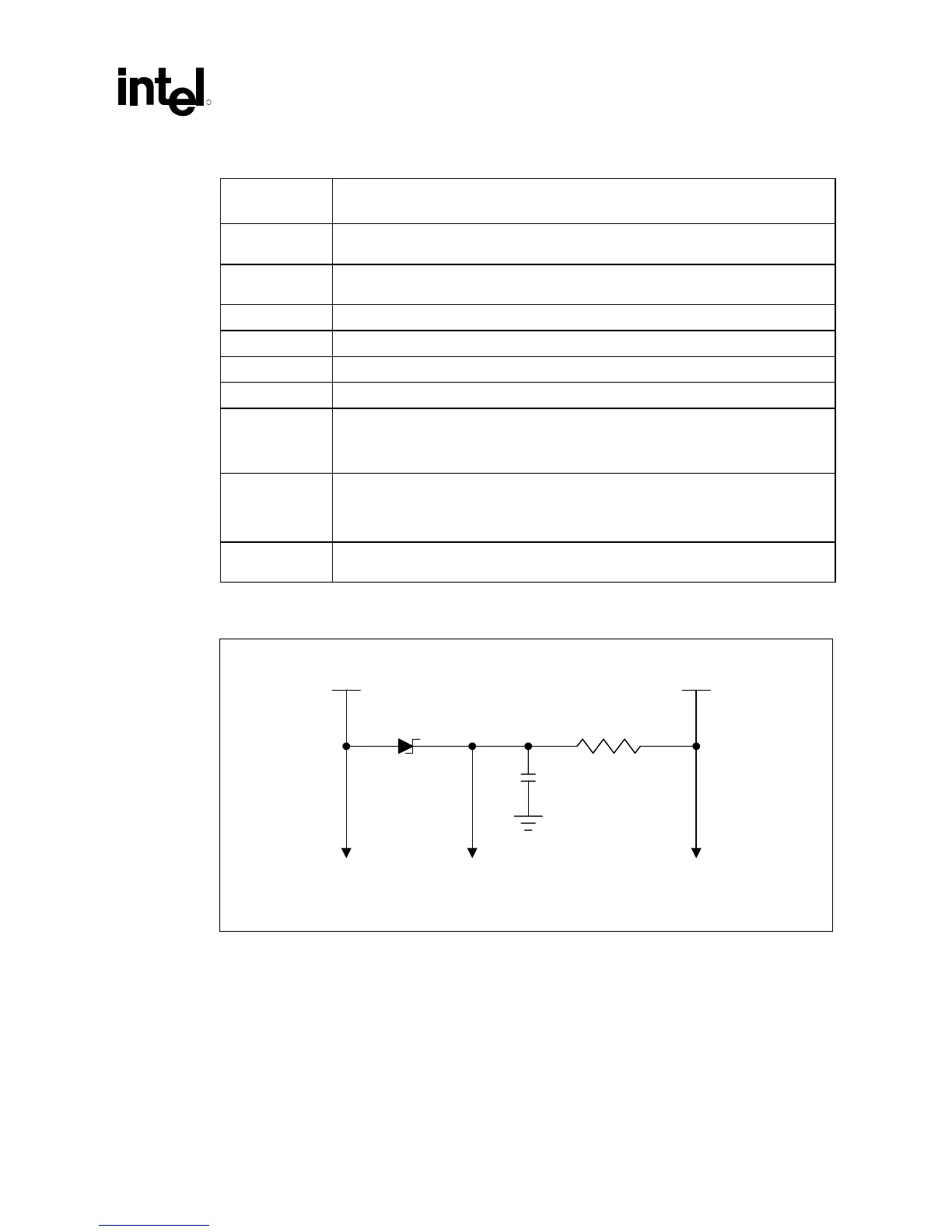
5V_REF • 5VREF is the reference voltage for 5V tolerant inputs in the ICH. Tie to pins
VREF[2:1]. 5VREF must power up before or simultaneous to VCC3_3. It must power
down after or simultaneous to VCC3_3. Refer to the figure below for an example
circuit schematic that may be used to ensure the proper 5VREF sequencing.
VCMOS • VCMOS power source must supply 1.5V and be generated by circuitry on the
motherboard. See Appendix A: Customer Reference Board (CRB).
Figure 79. V5REF Circuitry
Vcc Supply
(3.3V)
5V Supply
To SystemV
REF
To System
1 K
Ω
1.0 uF
vref_circuit