System Design Checklist
R
156 Intel
®
815 Chipset Platform Design Guide
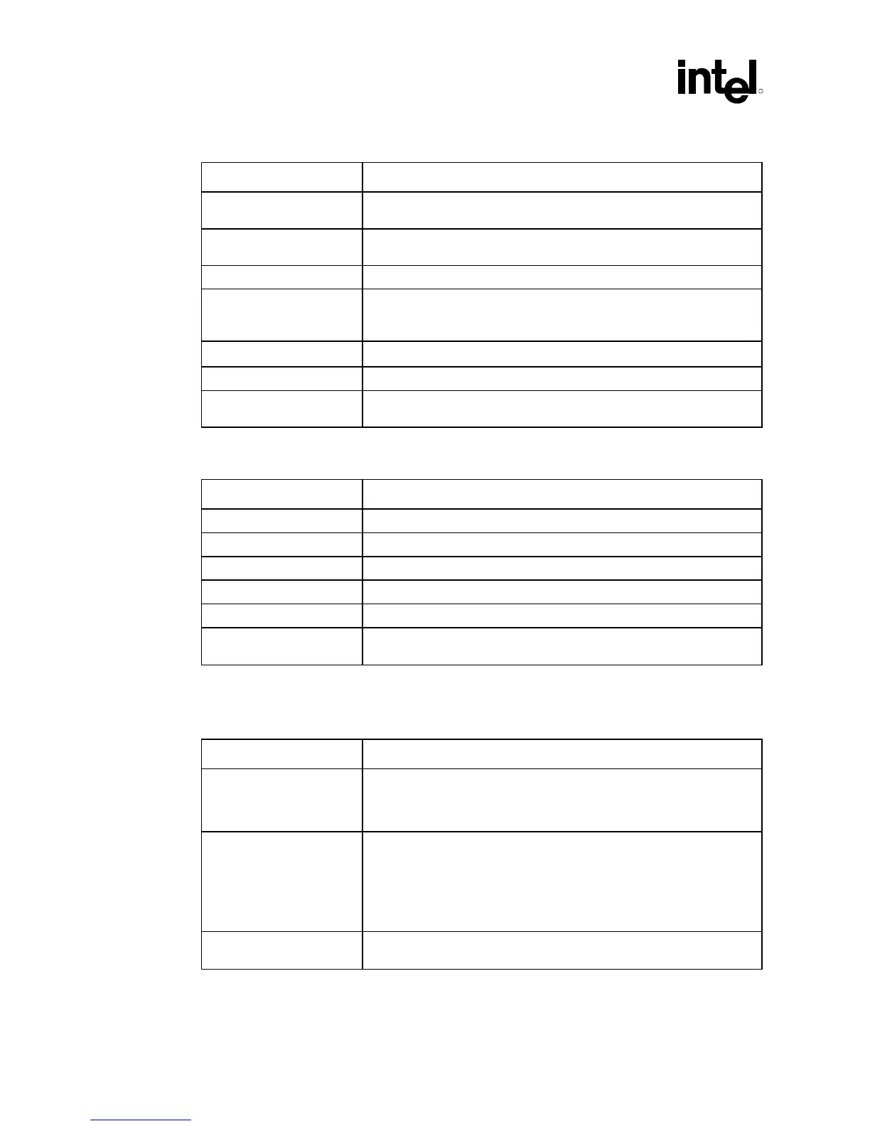
13.2.2 CMOS Checklist
Checklist Items Recommendations
IERR# • 150 Ω pull-up resistor to VCC
CMOS
if tied to custom logic, or leave as No
Connect (not used by chipset)
PREQ# • 200–300 Ω pull-up resistor to VCC
CMOS
/ Connect to ITP or else leave as
No Connect.
THERMTRIP# • See Section 5.3.1.
A20M#, IGNNE#, INIT#,
INTR, NMI, SLP#, SMI#,
STPCLK#
• 150 Ω pull-up to VCMOS / Connect to ICH
FERR#
• Requires 150 Ω pull-up to VCC
CMOS
/Connect to ICH.
FLUSH# • Requires 150 Ω pull-up to VCC
CMOS.
(Not used by chipset.)
PWRGOOD • 330 Ω pull-up to VCC2_5 /1.8 kΩ pull-down resistor to ground /Connect
to POWERGOOD logic.
13.2.3 TAP Checklist for 370-Pin Socket Processors
Checklist Items Recommendations
TCK • 39 Ω pull-down resistor to ground / Connect to ITP.
TMS • 39Ω pull-up resistor to VCMOS / Connect to ITP
TDI • 200–330 Ω pull-up resistor to VCMOS / Connect to ITP.
TDO • 150 Ω pull-up resistor to VCMOS / Connect to ITP.
TRST# • 500-680 Ω pull-down resistor to ground / Connect to ITP.
PRDY# • Pull-up resistor that matches GTL characteristic impedance to VTT /
240
Ω series resistor to ITP.
NOTE: Resistors need to be placed within 1 inch of the TAP connector.
13.2.4 Miscellaneous Checklist for 370-Pin Socket Processors
Checklist Items Recommendations
BCLK • Connect to clock generator. / 22–33 Ω series resistor (though OEM
needs to simulate based on driver characteristics). To reduce pin-to-pin
skew, tie host clock outputs together at the clock driver then route to the
GMCH and processor.
BSEL0 • Case 1 (66/100/133 MHz support): 1 kΩ pull-up resistor to 3.3V.
Connect to Intel
®
CK-815 SEL0 input. Connect to GMCH LMD29 pin via
10 k
Ω series resistor.
• Case 2 (100/133 MHz support): 1 kΩ pull-up resistor to 3.3V. Connect
to PWRGOOD logic such that a logic Low on BSEL0 negates
PWRGOOD.
BSEL1 • 1 kΩ pull-up resistor to 3.3V. Connect to Intel CK-815 REF pin via 10 kΩ
series resistor. Connect to GMCH LMD13 pin via 10 k
Ω series resistor.