System Bus Design Guidelines
R
50 Intel
®
815 Chipset Platform Design Guide
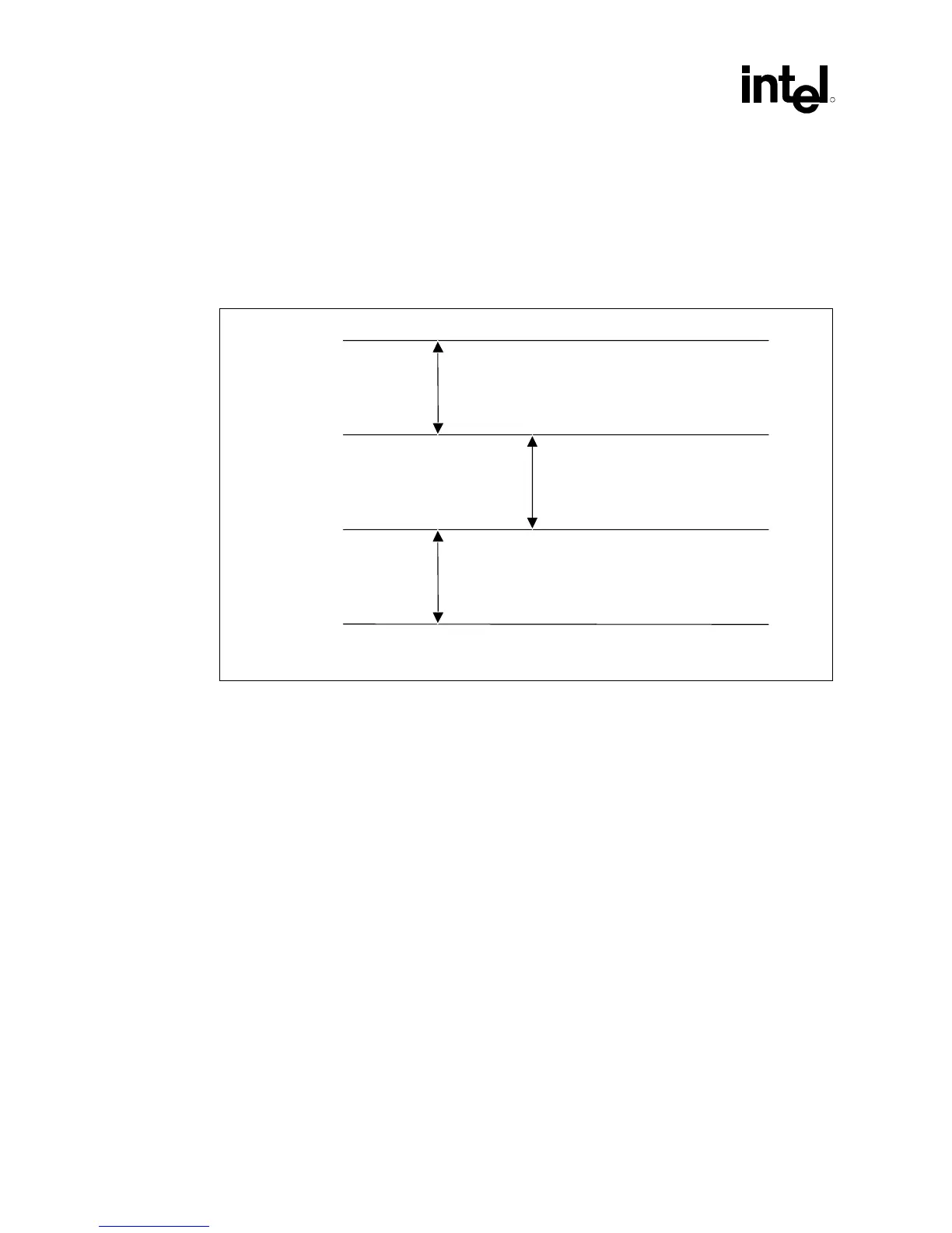
5.2.1.2 THRMDP and THRMDN
These traces (THRMDP and THRMDN) route the processor’s thermal diode connections. The
thermal diode operates at very low currents and may be susceptible to cross-talk. The traces should
be routed close together to reduce loop area and inductance.
Figure 21. Routing for THRMDP and THRMDN
1 — Maximize (min. – 20 mils)
1 — Maximize (min. – 20 mils)
2 — Minimize
Signal Y
THRMDP
THRMDN
Signal Z
bus_routing_thrmdp-thrmdn
NOTES:
1. Route these traces parallel and equalize lengths within
±0.5 inch.
2. Route THRMDP and THRMDN on the same layer.
5.2.1.3 Additional Routing and Placement Considerations
• Distribute VTT with a wide trace. A 0.050 inch minimum trace is recommended to minimize
DC losses. Route the VTT trace to all components on the host bus. Be sure to include
decoupling capacitors.
• The VTT voltage should be 1.5V ± 3% for static conditions, and 1.5V ± 9% for worst-case
transient conditions when the Pentium III processor (CPUID=068xh) or Celeron processor
(CPUID=068xh) is present in the socket. If a future 0.13 micron socket 370 processor is being
used, the VTT voltage should then be 1.25V ± 3% for static conditions, and 1.25V ± 9% for
worst-case transient conditions.
• Place resistor divider pairs for VREF generation at the GMCH component. VREF also is
delivered to the processor.