System Design Checklist
R
Intel
®
815 Chipset Platform Design Guide 163
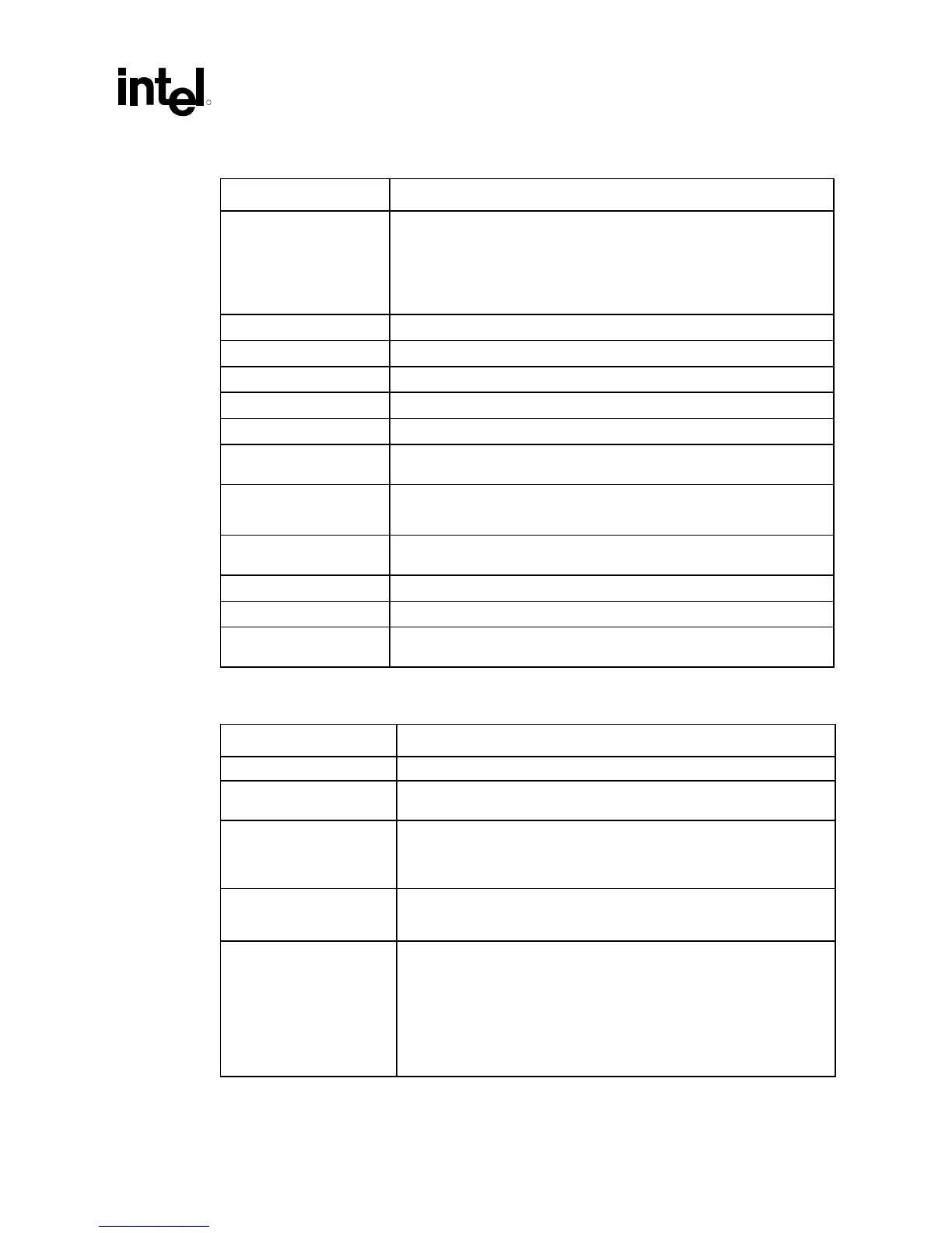
13.4.4 IDE Checklist
Checklist Items Recommendations
PDCS3#, SDCS3#,
PDA[2:0], SDA[2:0],
PDD[15:0], SDD[15:0],
PDDACK#, SDDACK#,
PRIOR#, SDIOR#,
PDIOW#, SDIOW#
• Connect from ICH to IDE Connectors. No external series termination
resistors required on those signals with integrated series resistors.
PDD7, SDD7 • Pull-down through a 10 kΩ resistor to GND.
PDREQ, SDREQ • Pull-down through a 5.6 kΩ resistor to GND.
PIORDY, SIORDY • Pull-up through a 1 kΩ resistor to VCC5
PDCS1#, SDCS1# • Connect from ICH to IDE Connectors
PRI_PD1, PRI_SD1 • Pull-down through a 470 Ω resistor to GND.
IDE_ACTIVE • From IDEACTP# and IDEACTS# connect to HD LED circuitry (see CRB
Schematic page 35)
CBLID#/PDIAG# • Refer to Section 10.2 for the correct circuit.
• NOTE: All ATA66 drives will have the capability to detect cables.
IDE Reset • This signal requires a 22 Ω–47 Ω series termination resistor and should
be connected to buffered PCIRST#.
IRQ14, IRQ15 • Need 8.2 kΩ resistor to 10 kΩ pull-up resistor to 5V.
CSEL • Pull-down to GND through 4.7 kΩ resistor (approximate).
IDEACTP#, IDEACTS# • For HD LED implementation use a 10 kΩ (approximate) pull-up resistor to
5V.
13.4.5 Miscellaneous ICH Checklist
Checklist Items Recommendations
RTC circuitry • Refer to Section 10.9 for exact circuitry.
PME#, PWRBTN#,
LAD[3..0]#/FWH[3..0]#
• No external pull-up resistor on those signals with integrated pull-ups.
SPKR • Optional strapping: Internal pull-up resistor is enabled at reset for
strapping after - reset the internal pull-up resistor is disabled. Otherwise
connect to motherboard speaker logic. (When strapped, use strong pull-
up, e.g., 2 k
Ω)
AC_SDOUT, AC_BITCLK • Optional strapping: Internal pull-up resistor is enabled at reset for
strapping after - reset the internal pull-up resistor is disabled. Otherwise
connect to AC’97 logic.
AC_SDIN[1:0] • Internal pull-down resistor is enabled only when the AC link hut-off bit in
the ICH is set.
• Use 10 kΩ (approximate) pull-down resistors on both signals if using
AMR.
• For onboard AC’97 devices, use a 10 kΩ (approximate) pull-down
resistor on the signal that is not used.
• Otherwise, connect to AC’97 logic.