System Bus Design Guidelines
R
64 Intel
®
815 Chipset Platform Design Guide
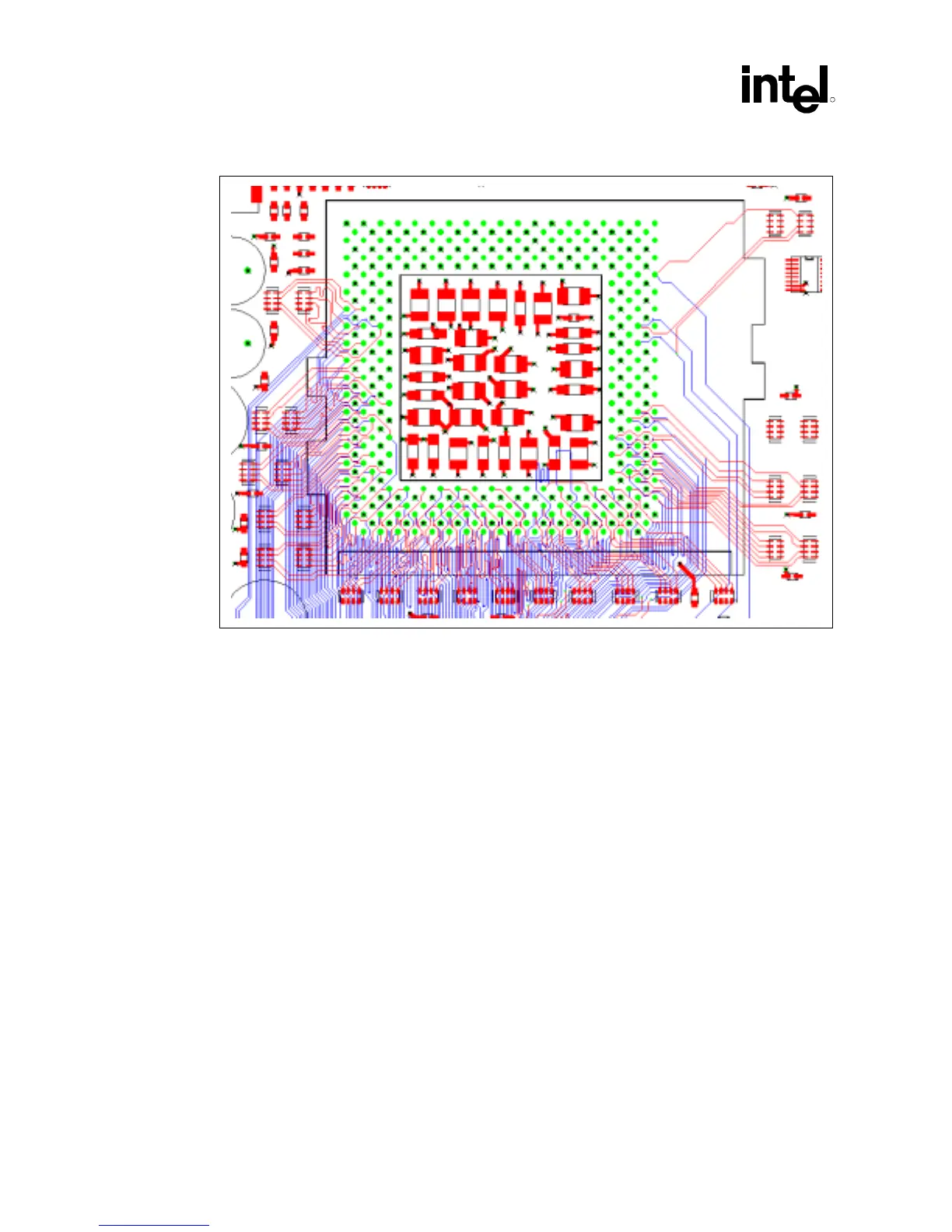
Figure 30. Capacitor Placement on the Motherboard
5.11.2 VTT Decoupling Design
For Itt = 2.3 A (maximum)
• Twenty 0.1 µF capacitors in 0603 packages placed as closed as possible to the processor VTT
pins. The capacitors are shown on the exterior of the previous figure.
5.11.3 VREF Decoupling Design
• Four 0.1 µF capacitors in 0603 package placed near VREF pins (within 500 mils).