System Design Checklist
R
Intel
®
815 Chipset Platform Design Guide 165
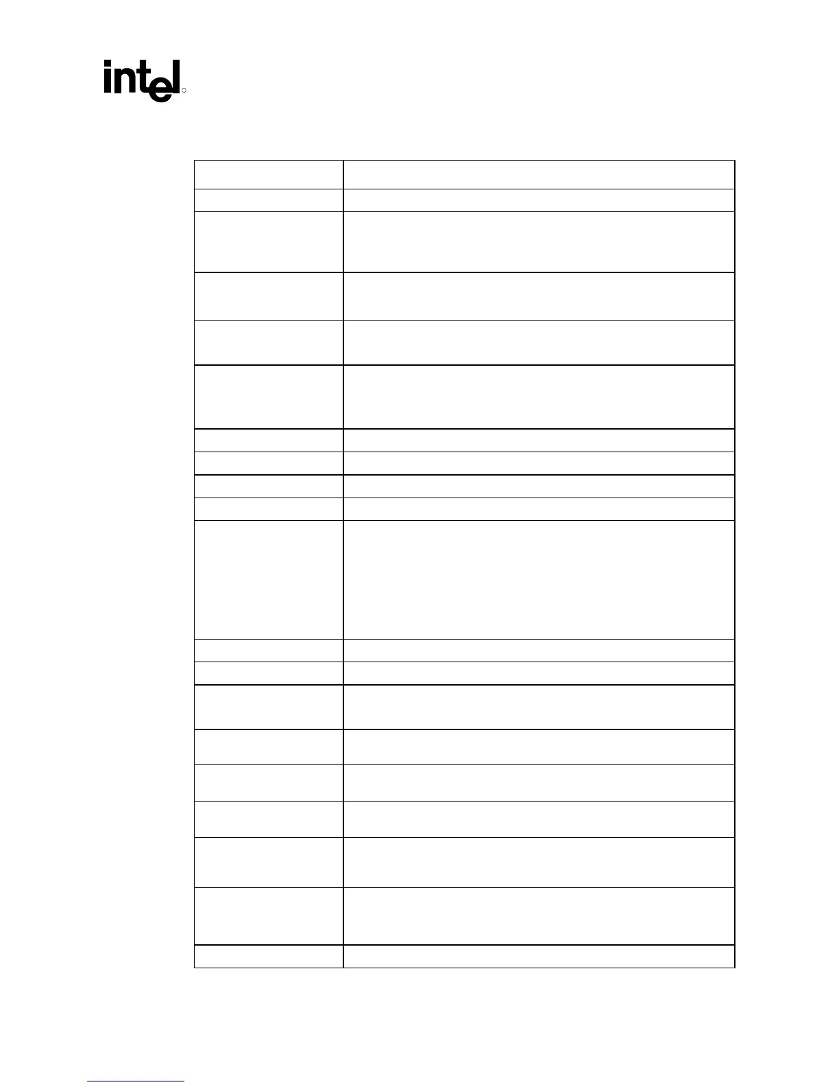
13.5 LPC Checklist
Checklist Items Recommendations
RCIN# • Pull-up through 8.2 kΩ resistor to VCC3_3
LPC_PME# • Pull-up through 8.2 kΩ resistor to VCC3_3. Do not connect LPC PME# to
PCI PME#. If the design requires the Super I/O to support wake from any
suspend state, connect Super I/O LPC_PME# to a resume well GPI on
the ICH.
LPC_SMI# • Pull-up through 8.2 kΩ resistor to VCC3_3. This signal can be connected
to any ICH GPI. The GPI_ROUTE register provides the ability to generate
an SMI# from a GPI assertion.
TACH1, TACH2 • Pull-up through 4.7 kΩ resistor to VCC3_3
• Jumper for decoupling option (decouple with 0.1 µF capacitor).
J1BUTTON1,
JPBUTTON2,
J2BUTTON1,
J2BUTTON2
• Pull-up through 1 kΩ resistor to VCC5. Decouple through 47 pF capacitor
to GND
LDRQ#1 • Pull-up through 4.7 kΩ resistor to VCC3SBY
A20GATE • Pull-up through 8.2 kΩ resistor to VCC3_3
MCLK, MDAT • Pull-up through 4.7 kΩ resistor to PS2V5.
L_MCLK, L_MDAT • Decoupled using 470 pF to ground
RI#1_C, CTS0_C,
RXD#1_C, RXD0_C,
RI0_C, DCD#1_C,
DSR#1_C, DSR0_C,
DTR#1_C, DTR0_C,
DCD0_C, RTS#1_C,
RTS0_C, CTS#1_C,
TXD#1_C, TXD0_C
• Decoupled using 100 pF to GND
L_SMBD • Pass through 150 Ω resistor to Intel
®
82559
SERIRQ • Pull-up through 8.2 kΩ to VCC3_3
SLCT#, PE, BUSY, ACK#,
ERROR#
• Pull-up through 2.2 kΩ resistor to VCC5_DB25_DR
• Decouple through 180 pF to GND
LDRQ#0 • Connect to ICH from SIO. This signal is actively driven by the Super I/O
and does not require a pull-up resistor.
STROBE#, ALF#,
SLCTIN#, PAR_INIT#
• Signal passes through a 33 Ω resistor and is pulled up through 2.2 kΩ
resistor to VCC5_DB25_CR. Decoupled using a180 pF capacitor to GND.
PWM1, PWM2 • Pull-up to 4.7 kΩ to VCC3_3 and connected to jumper for decouple with
0.1
µF capacitor to GND.
INDEX#, TRK#0,
RDATA#, DSKCHG#,
WRTPRT#
• Pull-up through 1 kΩ resistor to VCC5
PDR0, PDR1, PDR2,
PDR3, PDR4, PDR5,
PDR6, PDR7
• Passes through 33 Ω resistor
• Pull-up through 2.2 kΩ to VCC5_DB5_CRDecouple through 180 pF
capacitor to GND
SYSOPT • Pull-down with 4.7 kΩ resistor to GND or IO address of 02Eh