Universal Socket 370 Design
R
38 Intel
®
815 Chipset Platform Design Guide
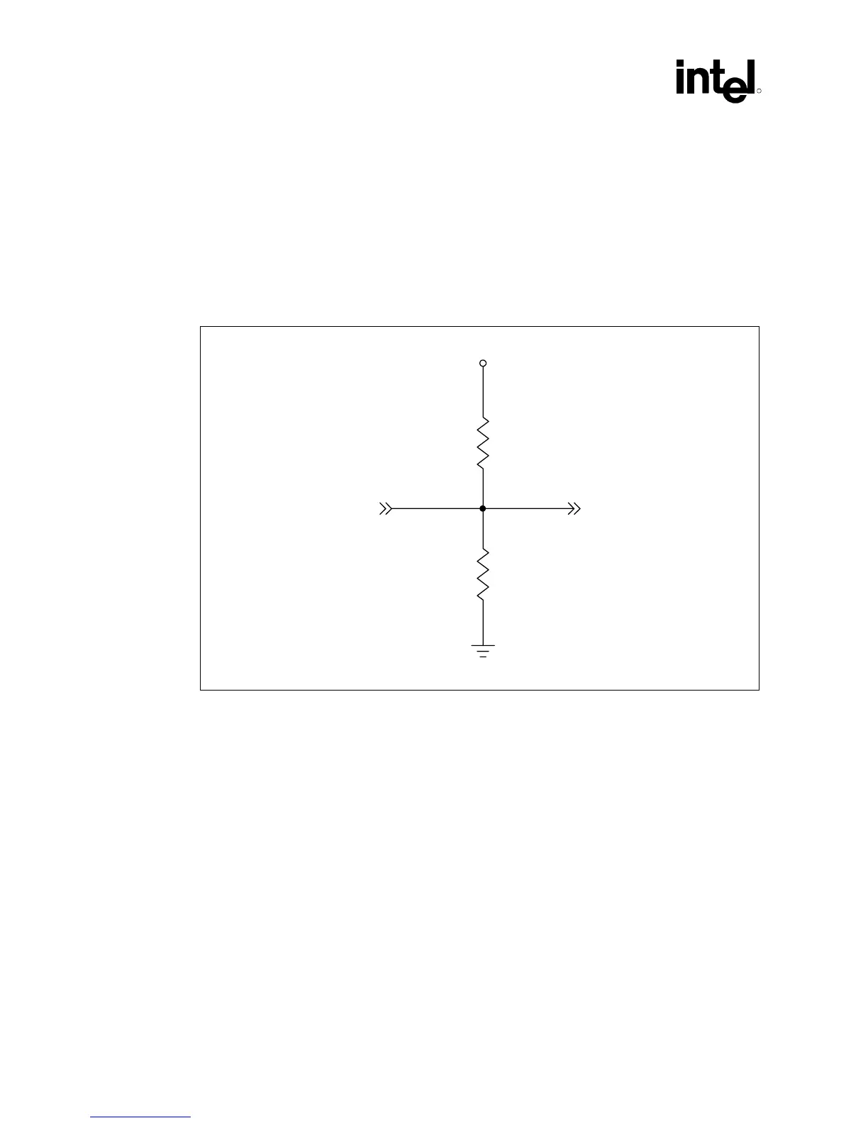
4.2.8 Processor Signal PWRGOOD
The processor signal PWRGOOD is specified at different voltage levels depending on whether it
is a Pentium III processor (CPUID=068xh) / Celeron processor (CPUID=068xh), or whether it is a
future 0.13 micron socket 370 processor. As there is an overlap between the ranges of accepted
voltage levels for these two processor groups, a resistor divider network that provides 2.1V will
satisfy the requirements of all supported processors. See Figure 14 for an example implementation.
Figure 14. Resistor Divider Network for Processor PWRGOOD
PWRGOOD to Processor
VCC2_5
PW RGOOD from ICH2
330
Ω
1.8 ΚΩ
PWRGOOD_Divider