System Memory Design Guidelines
R
Intel
®
815 Chipset Platform Design Guide 71
6.2.2 System Memory 2-DIMM Layout Guidelines
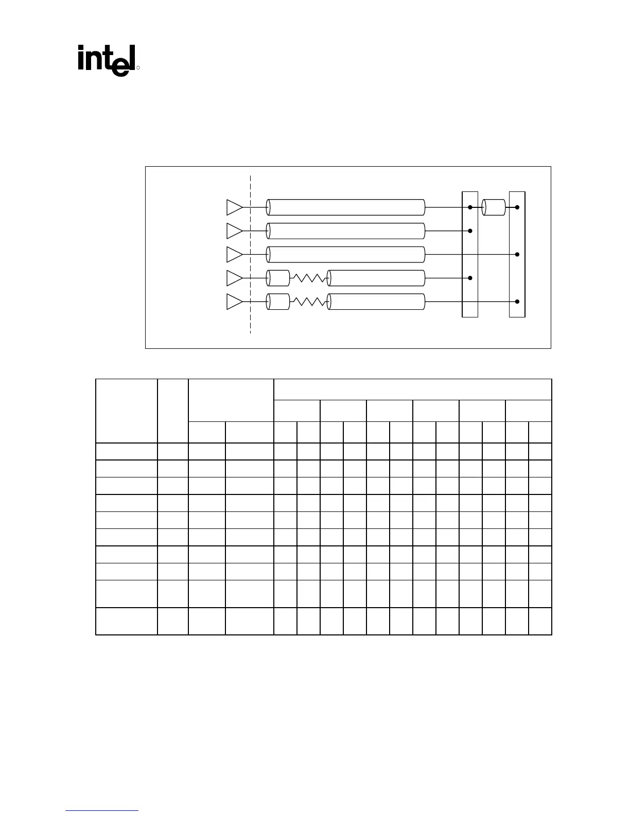
Figure 36. System Memory 2-DIMM Routing Topologies
Topology 1
82815
Topology 2
Topology 3
Topology 4
Topology 5
sys_mem_2DIMM_routing_topo
A
C
D
F
F
10
Ω
10
Ω
E
E
B
DIMM 0 DIMM 1
Table 18. System Memory 2-DIMM Solution Space
Trace Lengths (inches) Trace (mils)
A B C D E F
Signal Top.
Width Spacing Min. Max. Min. Max. Min. Max. Min. Max. Min. Max. Min. Max.
SCS[3:2]# 3 5 10 1 4.5
SCS[1:0]# 2 5 10 1 4.5
SMAA[7:4] 4 10 10 0.4 0.5 2 4
SMAB[7:4]# 5 10 10 0.4 0.5 2 4
SCKE[3:2] 3 10 10 3 4
SCKE[1:0] 2 10 10 3 4
SMD[63:0] 1 5 10 1.75 4 0.4 0.5
SDQM[7:0] 1 10 10 1.5 3.5 0.4 0.5
SCAS#, SRAS#,
SWE#
1 5 10 1 4.0 0.4 0.5
SBS[1:0],
SMAA[12:8,3:0]
1 5 10 1 4.0 0.4 0.5
In addition to meeting the spacing requirements outlined in Table 18, system memory signal trace
edges must be at least 30 mils from any other non-system memory signal trace edge.